Electrical Engineering > QUESTIONS & ANSWERS > ENME 351 – Electronics & Instrumentation II: Fall 2020 Department of Mechanical Engineering. Univ (All)
ENME 351 – Electronics & Instrumentation II: Fall 2020 Department of Mechanical Engineering. University of Maryland. Assignment 9 - Questions and Solutions
Document Content and Description Below
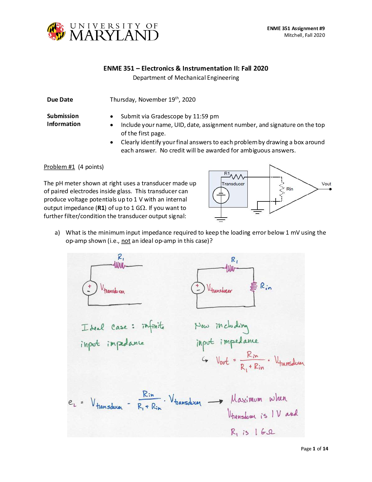
ENME 351 – Electronics & Instrumentation II: Fall 2020 Department of Mechanical Engineering. University of Maryland. Assignment 9 - Questions and Solutions ENME 351 – Electronics & Instrumentati... on II: Fall 2020 Department of Mechanical Engineering Problem #1 (4 points) The pH meter shown at right uses a transducer made up of paired electrodes inside glass. This transducer can produce voltage potentials up to 1 V with an internal output impedance (R1) of up to 1 G. If you want to further filter/condition the transducer output signal: a) What is the minimum input impedance required to keep the loading error below 1 mV using the op-amp shown (i.e., not an ideal op-amp in this case)? Problem #2 (6 points) A temperature sensor is put into the following circuit as Rsensor. An identical, matching reference sensor Rref is held at a constant 37oC. Problem #3 (4 points) For each of the motor driver circuits below, answer the following questions. The nominal supply voltage Vmotor = 12 V, the motor resistance Rm = 115 , the motor torque constant KT = 6.61 mN-m/A, and the motor speed constant Ke = 0.692 V/krpm (Faulhaber Series 1516 012S motor). The transistors are each 2N7000 series. Use the typical values and the conditions that most closely approximate each case. Problem #4 (2 points) The rotor inductance for the Faulhaber Series 1516 012S motor is 900 μH. If the current through a transistor switch changes at a rate of 1 A/μsec when switched off, what is the voltage generated across the rotor inductance? As an engineer, does this voltage level cause you to be alarmed? If so, what can be done to prevent damage to the circuit? Problem #5 (4 points) Consider the motor circuit at right. Sketch the time-domain signals required at A and B to turn the motor forward at 50% full speed and reverse at 75% full speed. Label plot axes and all relevant axis values. Assume that the signals are provided by an Arduino Uno, that speed is proportional to voltage and that the threshold voltage for the transistors is 3.3V, and a VPWM period of 1 msec. [Show More]
Last updated: 2 years ago
Preview 1 out of 14 pages
Buy this document to get the full access instantly
Instant Download Access after purchase
Buy NowInstant download
We Accept:

Reviews( 0 )
$9.50
Can't find what you want? Try our AI powered Search
Document information
Connected school, study & course
About the document
Uploaded On
Apr 20, 2023
Number of pages
14
Written in

Additional information
This document has been written for:
Uploaded
Apr 20, 2023
Downloads
0
Views
73