Physics > QUESTIONS & ANSWERS > University of Washington, Tacoma CEE220-HW8-Solution-VERIFIED BY EXPERTS-GRADED A+ (All)
University of Washington, Tacoma CEE220-HW8-Solution-VERIFIED BY EXPERTS-GRADED A+
Document Content and Description Below
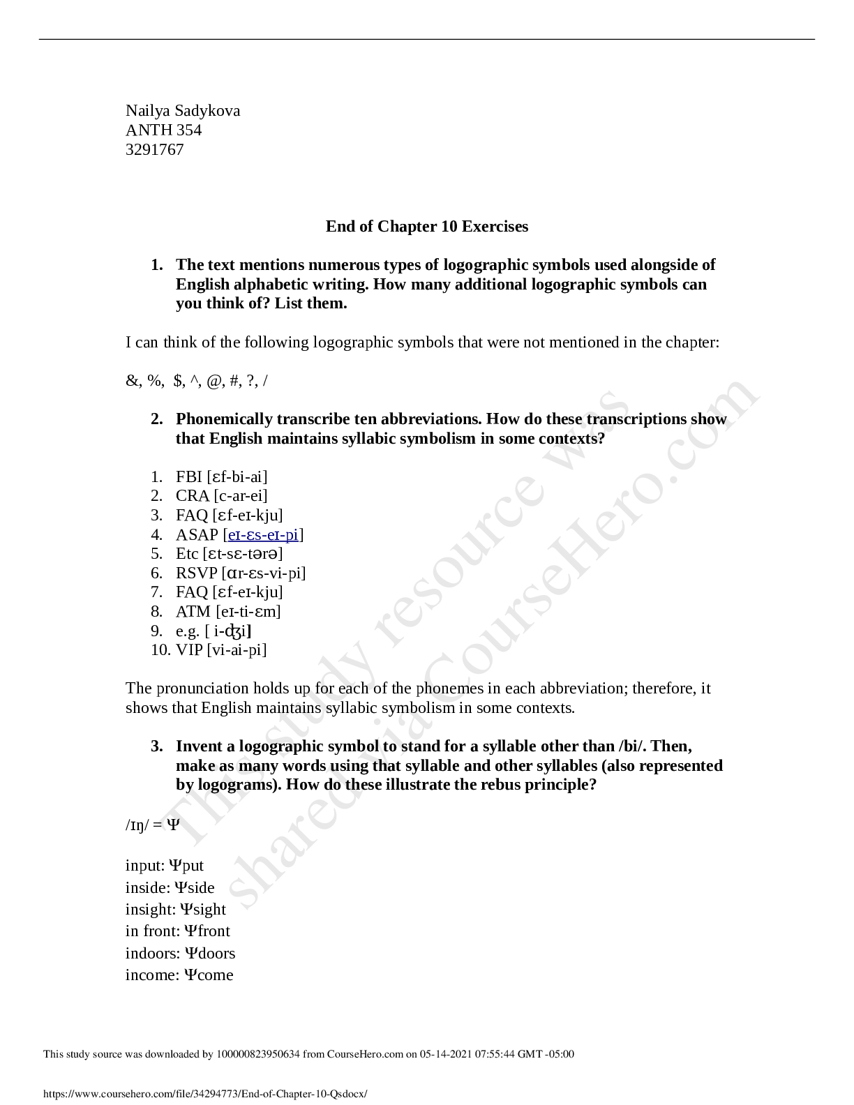
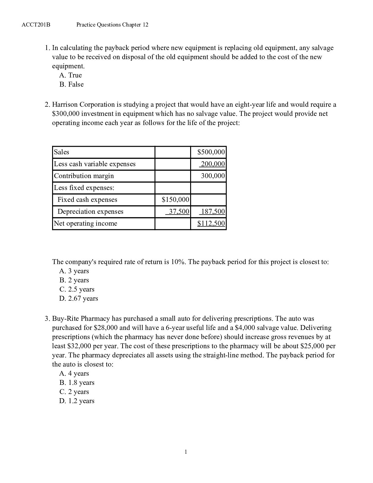
Homework Assignment No. 8 Spring 2016 Due: May 23th Reading Assignments: Please read the Beam handouts. Problem Set For all problems, write a problem statement, provide sketches, and comment on y... our thought process. Draw free body diagrams as applicable. Use the figures in your textbook indicated in each problem. 1. Bending of Retaining wall Cantilever concrete retaining walls are commonly used to hold water or soil pressures. The figure shown below indicates an application of such concrete walls in water reservoir construction. Such walls should be designed in such a way no tension stress occurs in the wall. The retaining wall shown in the figure can be simplified as a rectangular solid concrete wall. Determine the minimum thickness of the wall, if there is no tension at the base of the wall. (γwater = 62 Ibf=ft3; γconcrete = 250 Ibf=ft3; h = 40 ft) Hint: The wall is similar to a cantilever beam subjected to its self weight and water pressure. You need to superpose bending stress due to water pressure and normal stress due to wall’s self weight to determine the minimum thickness of the wall. [] [] 1CEE 220 2 Solution: Unit width of 1 ft was considered to find loads and the moment of inertia of the wall. Mwater is a moment at the base of the wall due to water pressure. σt is the tension stress due to Mwater. σnormal is the compression stress at the base due to self weight of the wall. Mwater = γwater(h2)(1 ft) 2 :(h=3) = 661333 lb − ft σt = Mwater:(t=2) I = Mwater:(t=2) (1):(t)3=12 = 3968000=t2 σnormal = −γconcrete(h) = −10000 lb=ft2 σnormal + σt = 0 t = 19:9 ft 2. Bending of Wide-Flange Beam Consider the wide-flange beam section shown in the figure below. 2 in 14 in 2 in 1 in A M B C D 8 in 7 in 4 in (a) Determine the percentage of the moment M that is resisted by the top and bottom flanges of the beam. (b) Determine the direction (sign) and magnitude of the moment M that should be applied to the beam to cause a tensile stress of 22 ksi at point A. Draw the stress distribution acting on the cross section. (c) Determine the maximum bending normal stress, σmax and also the bending stress at points A, B, C, and D in the beam, if the moment M is equal to 20 kip·ft (Moment is applied as shown in figure). (d) Determine the resultant force the bending stress on the top flange creates if the moment M is equal to 10 kip·ft (Moment is applied as shown in figure [Show More]
Last updated: 2 years ago
Preview 1 out of 13 pages

Buy this document to get the full access instantly
Instant Download Access after purchase
Buy NowInstant download
We Accept:

Reviews( 0 )
$9.00
Can't find what you want? Try our AI powered Search
Document information
Connected school, study & course
About the document
Uploaded On
May 28, 2021
Number of pages
13
Written in

Additional information
This document has been written for:
Uploaded
May 28, 2021
Downloads
0
Views
55


.png)

.png)