Civil Engineering > QUESTIONS & ANSWERS > University of New South Wales CVEN CVEN 3304 The point loads are placed at the fixed positions sh (All)
University of New South Wales CVEN CVEN 3304 The point loads are placed at the fixed positions shown in the figure and they are live loads. A B D E *- W C (centre) C a Asc f's = 32 Mpa b f'of =...
Document Content and Description Below
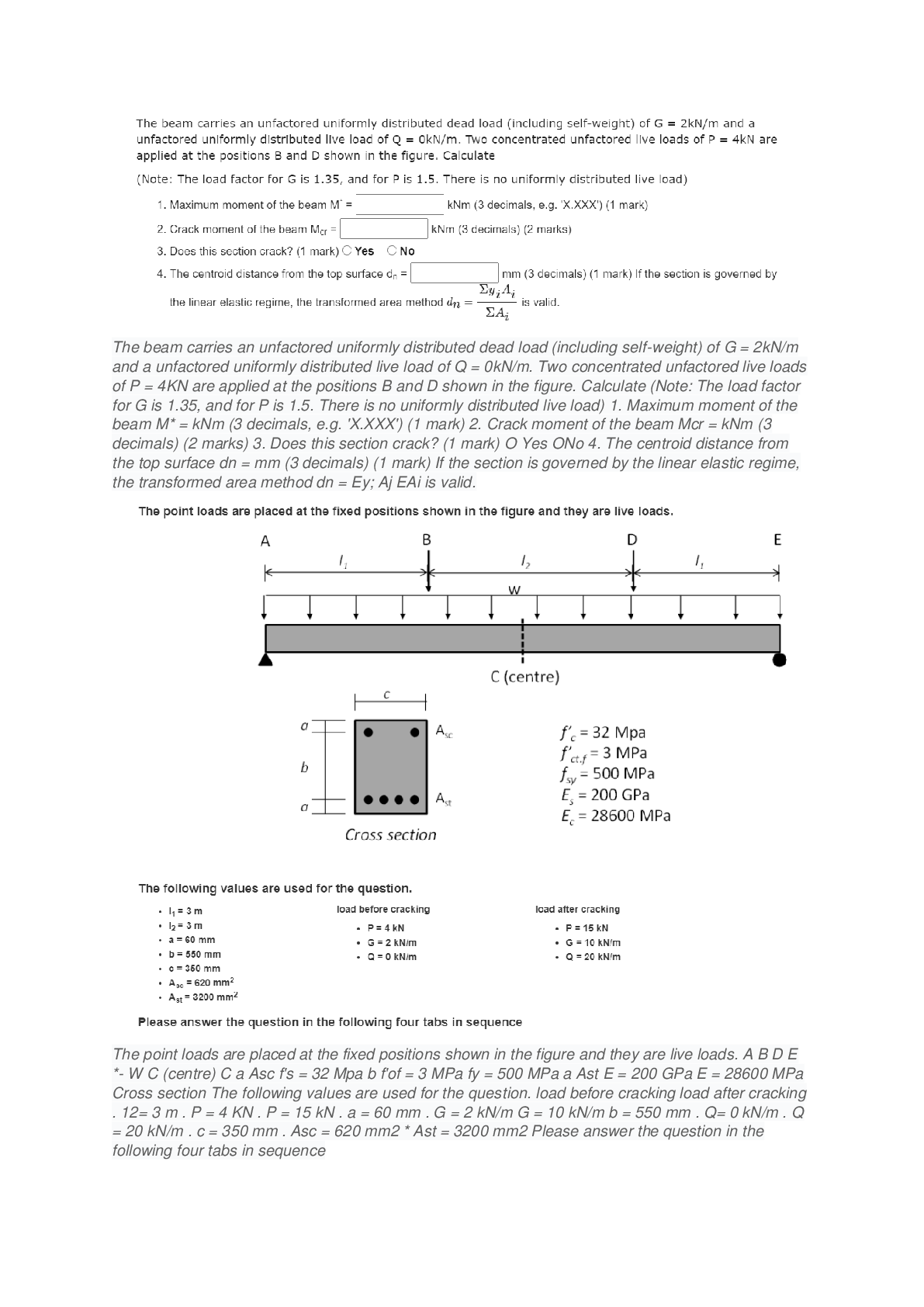
Question Answered step-by-step The picture below have all the message I have I don't know how to... The picture below have all the message I have 屏幕截图(30).png Image transcription text ... The point loads are placed at the fixed positions shown in the figure and they are live loads. A B D E *- W C (centre) C a Asc f's = 32 Mpa b f'of = 3 MPa fy = 500 MPa a Ast E = 200 GPa E = 28600 MPa Cross section The following values are used for the question. load before cracking load after cracking . 12= 3 m . P = 4 KN . P = 15 kN . a = 60 mm . G = 2 kN/m G = 10 kN/m b = 550 mm . Q= 0 kN/m . Q = 20 kN/m . c = 350 mm . Asc = 620 mm2 * Ast = 3200 mm2 Please answer the question in the following four tabs in sequence I don't know how to solve the question blow Q1 屏幕截图(34).png Image transcription text The beam carries an unfactored uniformly distributed dead load (including self-weight) of G = 2kN/m and a unfactored uniformly distributed live load of Q = 0kN/m. Two concentrated unfactored live loads of P = 4KN are applied at the positions B and D shown in the figure. Calculate (Note: The load factor for G is 1.35, and for P is 1.5. There is no uniformly distributed live load) 1. Maximum moment of the beam M* = kNm (3 decimals, e.g. 'X.XXX') (1 mark) 2. Crack moment of the beam Mcr = kNm (3 decimals) (2 marks) 3. Does this section crack? (1 mark) O Yes ONo 4. The centroid distance from the top surface dn = mm (3 decimals) (1 mark) If the section is governed by the linear elastic regime, the transformed area method dn = Ey; Aj EAi is valid. Q2 屏幕截图(32).png Image transcription text Now, the live load increases gradually and the moment at the critical section just exceeds the cracking moment (Mar) but the compressive section ofthe concrete is still governed by the linear elastic region. It should be noted that in the flexural design, the cracking of the concrete section starts where the tensile stress reaches the tensile strength. It is assumed that the cracks then propagate rapidly up to the entire tension section (up to the neutral axis) and this cracked concrete section cannot resist the tension. In reality, concrete sections between the primary cracks can still resist some tensile stresses as shown in the figure below, which should be considered in the displacement design. However, in the flexure design, we design the critical section where the largest moment occurs and thus it is reasonable to have such primary cracks in this critical section. . . . 35': In the linear elastic region, the transformed area method dn = is still valid. However, we may solve the quadratic equation for 2.4,. calculating the neutral axis distance from the top surface. Stress profile (concrete) Stress profile (concrete) Cross section before cracking Cross section just after cracking Longltudlnal Sectlon concrete in tension 1. The new neutral axis is in the cracked section under the elastic region on the compressive section. d,I (distance to the top surface) = E mm (3 decimals) {2 marks} 2. Cracked second moment of areas It, = x105 mrn'1 (3 decimals) (2 marks) Q3 屏幕截图(33).png Image transcription text The applied loads keep increasing and the concrete section is now governed by the non-linear regime. The neutral axis moves upward and the concrete compressive section has the curvilinear distribution of compressive stresses, which requires the integration of the stress to compute the neutral axis and the ultimate nominal moment. To avoid the complex calculation, the Whitney stress block is introduced during the class. It should be noted that this ultimate strength stage is the condition for the flexural design. Thus, when we design the beam in terms of bending, in most cases, we can directly consider this ultimate condition without the previous linear stage. N.A cracks Ast Stress profile (concrete) Stress profile (concrete) Cross section before cracking Cross section just after cracking N.A > cracks At Stress profile (concrete) Cross section non-linear 1. Calculate the neutral axis distance from the top fibre (d) at the ultimate strength stage dn = mm (3 decimals) (2 marks) 2. Calculate the nominal ultimate moment (My) that this concrete section can carry using the given section dimensions and materials properties. My = kNm (3 decimals) (2 marks) the Q4 屏幕截图(35).png Image transcription text The beam now have to carry an unfactored dead load (including self-weight) of G = 10 kN/m and an unfactored live load of Q = 20 kN/m. Two concentrated unfactored live loads of P = 15 kN are applied at the positions shown in the figure. Determine if the design moment strength (QMu) exceeds the factored design moment M*, ( = 0.85. W = 1.2G + 1.5Q. 1. M= kNm (3 decimals) (1 mark) 2. Does the beam satisfy the design requirement? (1 mark) O Yes O No [Show More]
Last updated: 3 years ago
Preview 1 out of 16 pages
Buy this document to get the full access instantly
Instant Download Access after purchase
Buy NowInstant download
We Accept:

Reviews( 0 )
$11.00
Can't find what you want? Try our AI powered Search
Document information
Connected school, study & course
About the document
Uploaded On
Jul 10, 2021
Number of pages
16
Written in
All

Additional information
This document has been written for:
Uploaded
Jul 10, 2021
Downloads
0
Views
129


.png)

.png)
.png)
.png)


.png)