-BLAKEIntroduction to communications systems
Example 1.1
Calculate the wavelength in free space corresponding to a frequency of:
(a) 1 MHz (AM radio broadcast band)
(b) 27 MHz (CB radio band)
(c) 4 GHz (used for sat
...
-BLAKEIntroduction to communications systems
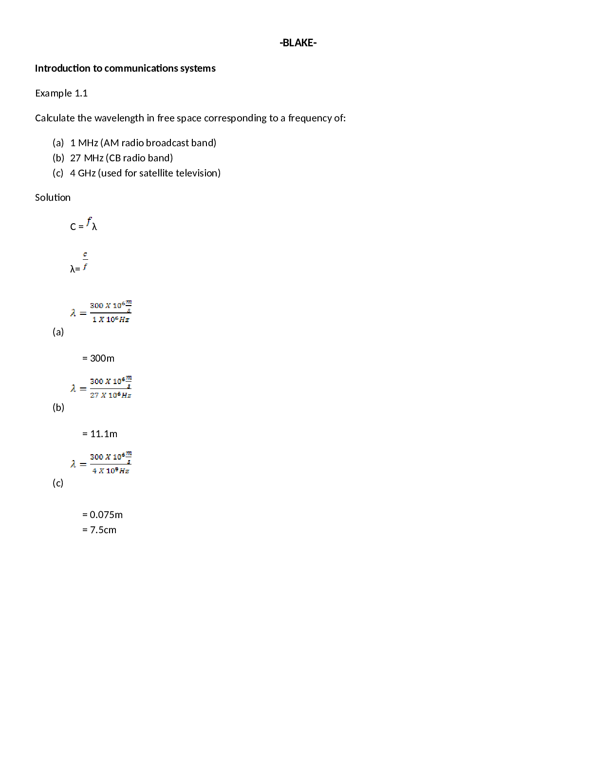
Example 1.1
Calculate the wavelength in free space corresponding to a frequency of:
(a) 1 MHz (AM radio broadcast band)
(b) 27 MHz (CB radio band)
(c) 4 GHz (used for satellite television)
Solution
C = λ
λ=
(a)
= 300m
(b)
= 11.1m
(c)
= 0.075m
= 7.5cm
Introduction to communications systems
Example1.4
A receiver has a noise power bandwidth of 10 kHz. A resistor that matches the receiver input impedance is
connected across its antenna terminals. What is the noise power contributed by that resistor in the receiver bandwidth,
if the resistor has temperature of 27 ⁰C
Solution
T(K)= T (⁰C) + 273
= 27 + 273
= 300 K
PN = kTB
= (1.38 X 10⁻²³ J/K (300 K) (10 X 103
Hz)
= 4.14 X 10⁻¹⁷ W
EXAMPLE 1.5
A 300Ω resistor is connected across the 300 Ω antenna input of a television receiver. The bandwidth of the
receiver is 6 MHz, and the resistor is at room temperature (293 K or 20⁰C or 68⁰F). Find the noise power voltage applied
to the receiver input.
Solution
PN = kTB
= (1.38 X 10⁻²³ J/K (300 K)(293 K) (6 X 10³
Hz)
= 24.2 X 10⁻¹⁵ W
= 24.2 fW
V N = √4kTBR
= √4 (1.38 X 10⁻²³ J/K)(293)(6 X 106
Hz) (300 Ω)
= 5.4 X 10⁻⁶ V
= 5.4µV
Introduction to communications systems
EXAPMLE 1.6
A diode noise generator is required to produce 10µV of noise in a receiver with an input impedance of 75 Ω,
resistive, and a noise power bandwidth 0f 200 kHz. (These values are typical of FM broadcast receivers.) What must be
current through the diode be?
Solution
V N
I N = I N = √2qI0B
R I
2
N = 2qI0B
10µV I
2
N
= =
75 Ω 2qB
= 0.133µA (0.133 X 10⁻⁶ A)2
=
2(1.6 X 10 -19 C)(200 X 103
Hz)
= 0.276 A or 276 mA
EXAMPLE 1.8
A receiver produces a noise power of 200 mW with no signal. The output level increases to 5W when a signal is
applied. Calculate (S + N)/N as a power ratio and in decibels.
Solution:
5 W
(S+N)/N=
0.2 W
= 25
(S+N)/N (dB) = 10 log 25
= 14dB
EXAMPLE 1.9
The signal power at the input to an amplifier is 100µW. at the output, the signal power is 1W and the noise
power is 30mW. What is the amplifier noise figure, as a ratio?
Solution:
100µW 100
(S/N)i = = 100 NF (ratio) = = 3
1µW 33.5
1µW
(S/N)o = = 33.3
0.03W
Introduction to communications systems
EXAMPLE 1.10
The signal at the input of an amplifier has an S/N of 42dB. If the amplifier has noise figure of 6dB, what is the S/N
at the output (in decibel)?
Solution
NF (dB) = (S/N)i(dB) - (S/N)o(dB)
(S/N)o(dB) = (S/N)i(dB) - NF (dB)
= 42 dB – 6 dB
= 36dB
EXAMPLE 1.11
An amplifier has a noise figure of 2 dB. What is its equivalent noise temperature?
Solution
NF (dB) = 10 log NF (ratio)
NF(dB)
NF (ratio)= antilog
10
= antilog 0.2
= 1.585
Teq = 290 (NF – 1)
= 290 (1.585 – 1)
= 169.6 K
Radio-Frequency Circuit
EXAMPLE 2.5
A varactor has a maximum capacitance of 80pF and is used in a tuned circuit with a 100 µH inductor.
(a) Find the resonant frequency with no tuning voltage applied
(b) Find the tuning necessary for the circuit to resonate at double the frequency found in part (a)
Solution
(a)
1
0 =
2π√LC
1
=
2π√(100 X 10-6)(80 X 10-12)
= 1.78 MHz
(b)
1 C0
0 = C =
2π√LC √1+2V
1 C0
0 = √1+2V =
4π2√LC C
1 C0
2
0 = 1+2V =
4π2 2
0 L C
1 (C0/ C) 2-1
= V =
4π2
(2 X 1..78 X 106
)
2 (100 X 10-6) 2
= 20 X 10-12 F (80/20) 2-1
= 20pF =
2
= 7.5 V
Radio-Frequency Circuit
EXAMPLE 2.6
A portable radio transmitter has to operate at temperature form – 50⁰C to 350⁰C if its signal is derived from a
crystal oscillator with a temperature coefficient of +1 ppm/degree C and it transmits at exactly 146 MHz at 20⁰C, find the
transmitting frequency at the two extremes of the operating temperature range.
Solution
T = 0 + k 0 (T – T0)
max =146 MHz + (146 MHz)(1 X 10
-6
)(35 -20)
= 146.00219 MHz
min =146 MHz + (146 MHz)(1 X 10
-6
)(-5 -20)
= 145.99635 MHz
EXAMPLE 2.7
Sine – wave signals with frequencies of 10 MHz 11MHz are applied to square – law mixer. What frequencies
appear at the output?
Solution
1 = 11MHz 2 2 = 22MHz 1 + 2 =21 MHz
2 = 11MHz 2 2 = 20MHz 1 - 2 = 1 MHz
EXAMPLE 2.8
A phase – locked loop has a VCO with a free – running frequency of 12 MHz. As the frequency of the reference
input is gradually raised from zero, the loop locks at 10MHz and comes out of lock again at 16 MHz.
(a) Find the capture range and lock range
(b) Suppose that the experiment is repeated, but this time the reference input begins with a very high frequency
and steadily moves downward. Predict the frequencies at which lock would be achieved and lost.
Solution
(a) (b)
Capture range = 2(12 MHz – 10 MHz) 12 MHz + 2 MHz =14 MHz
= 4 MHz 12 MHz – 4 MHz = 8 MHz
lock range = 2(16 MHz – 12 MHz)
= 8 MHz
Radio-Frequency Circuit
EXAMPLE 2.9
Configure a simple PLL synthesizer using a 10 MHz crystal so that it will generate the AM broadcast frequencies
from 540 to 1700 kHz.
Solution
OSC
Q=
ref
10 MHz
=
10 kHz
= 1000
0 = N ref
0
N =
ref
540 kHz
N =
10 kHz
= 54
1700 kHz
N =
10 kHz
= 170
Radio-Frequency Circuit
EXAMPLE 2.10
The synthesizer in Figure 2.40 has P = 10 and ref =10 kHz. Find the minimum frequency step size and compare it
with that obtained using a fixed divided-by-10 prescaler.
Solution
Step size = M ref
= 10 X 10 kHz
= 10 kHz
0 = (M+NP) ref
= (M+NP)10 kHz
’0 = (M+1+NP) ref
= (M+1+NP)10 kHz
’ 0 + 0 = (M+1+NP) 10 kHz – (M+NP)10kHz
= (M+1+NP – M - NP) 10 kHz
= 10kHz
EXAMPLE 2.11
A synthesizer of the type shown in figure 2.42 has ref =20 kHz and local oscillator operating at 10 Mhz. Find the
frequency range of the output as the value of N ranges from 10 to 100. Also find the minimum amount by which the
frequency can be varied.
[Show More]









.png)


.png)


