NURSING > A-Level Mark Scheme > ELEC240 ADC 2023 LATEST UPDATE (All)
ELEC240 ADC 2023 LATEST UPDATE
Document Content and Description Below
Last updated: 2 years ago
Preview 1 out of 3 pages
Instant download

Buy this Document to get the Full Access Instantly
Provided by Students Who Aced it
We Verify Document Content to Gurantee Accuracy
Reviews( 0 )
Document information
Connected school, study & course
About the document
Uploaded On
Aug 18, 2023
Number of pages
3
Written in
All

Additional information
This document has been written for:
Uploaded
Aug 18, 2023
Downloads
0
Views
240
Document Keyword Tags
Recommended For You
Get more on A-Level Mark Scheme »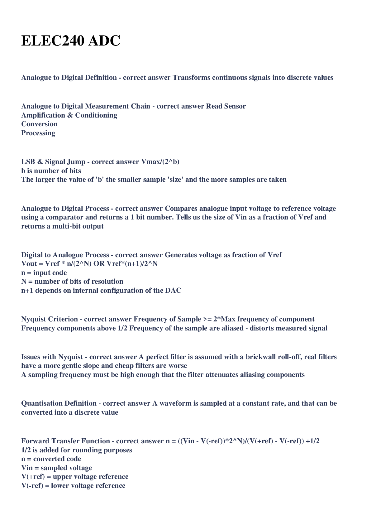

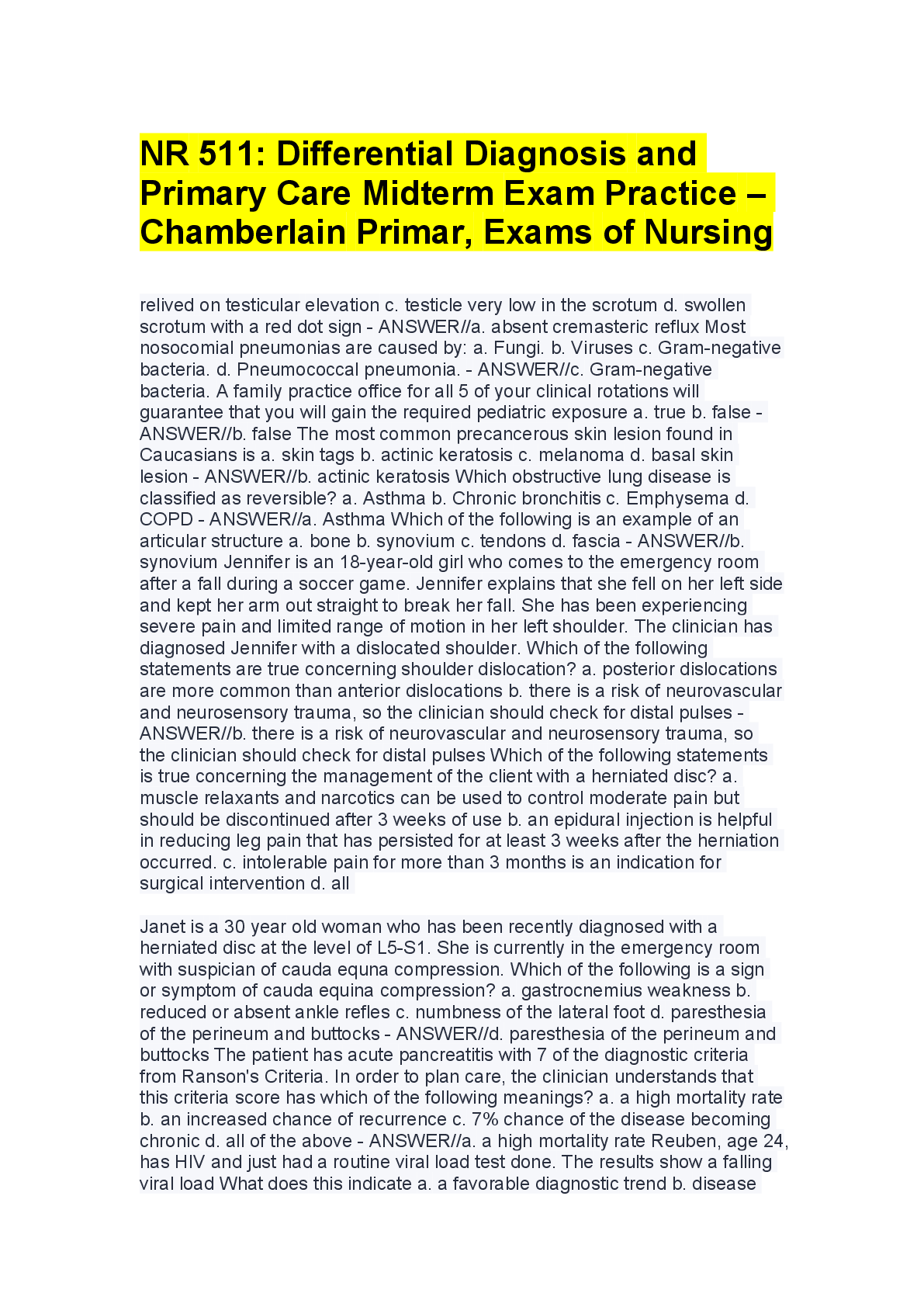
NR 511: Differential Diagnosis and Primary Care Midterm Exam P...
TEST BANK for Davis Advantage for Psychiatric Mental Health Nu...
Test Bank For Fundamentals of Nursing 11th Edition Potter Perr...
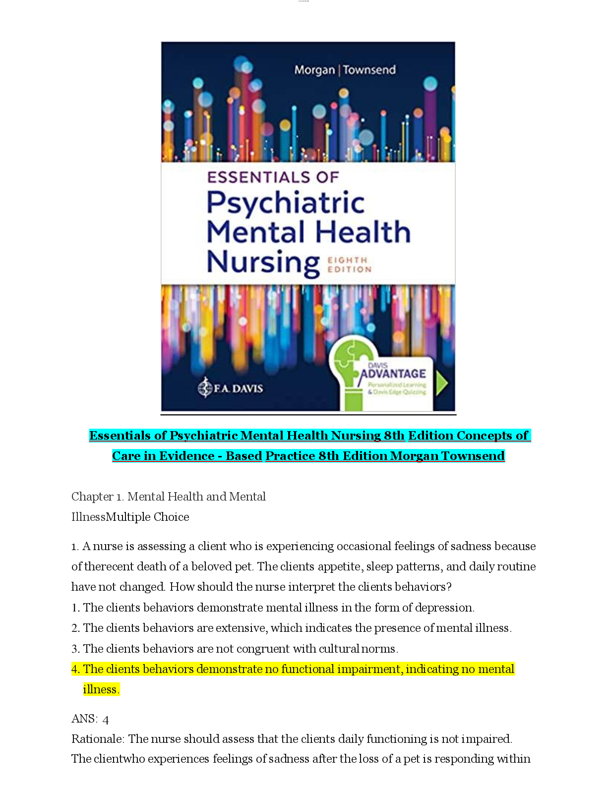
TEST BANK for Essentials of Psychiatric Mental Health Nursing:...
Essentials of Psychiatric Nursing 2nd Edition Boyd TEST BANK

TEST BANK for Essentials of Psychiatric Nursing 2nd Edition by...
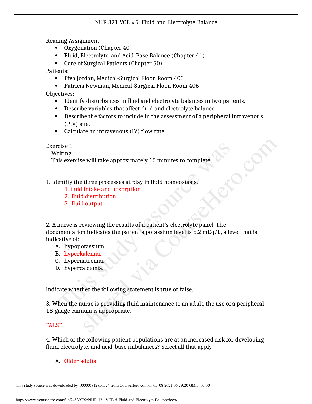
NUR 321 VCE #5 Fluid and Electrolyte Balance QUESTIONS AND ANS...

NUR 321 VCE # 1 Lesson 3- Critical Thinking in Nursing Practic...