Civil Engineering > STUDY GUIDE > ACI_315R_18_Guide_to_Presenting_Reinforcing_Steel_Design_Details 2020 | Guide_to_Presenting_Reinforc (All)
ACI_315R_18_Guide_to_Presenting_Reinforcing_Steel_Design_Details 2020 | Guide_to_Presenting_Reinforcing_Steel_Design_Details
Document Content and Description Below
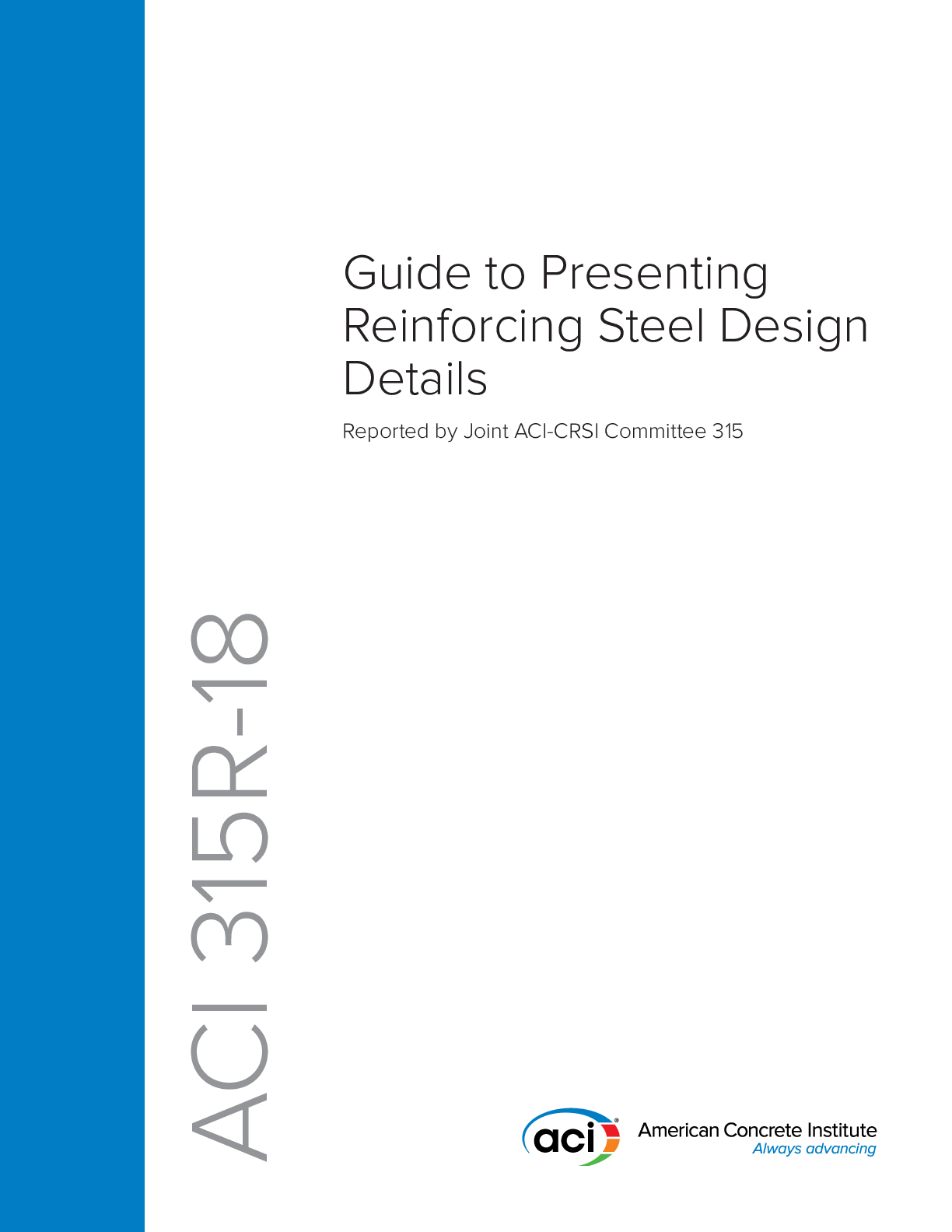
Guide to Presenting Reinforcing Steel Design Details Reported by Joint ACI-CRSI Committee 315 ACI 315R-18First Printing January 2018 ISBN: 978-1-945487-96-5 Guide to Presenting Reinforcing Stee... l Design Details Copyright by the American Concrete Institute, Farmington Hills, MI. All rights reserved. This material may not be reproduced or copied, in whole or part, in any printed, mechanical, electronic, film, or other distribution and storage media, without the written consent of ACI. The technical committees responsible for ACI committee reports and standards strive to avoid ambiguities, omissions, and errors in these documents. In spite of these efforts, the users of ACI documents occasionally find information or requirements that may be subject to more than one interpretation or may be incomplete or incorrect. Users who have suggestions for the improvement of ACI documents are requested to contact ACI via the errata website at http://concrete.org/Publications/ DocumentErrata.aspx. Proper use of this document includes periodically checking for errata for the most up-to-date revisions. ACI committee documents are intended for the use of individuals who are competent to evaluate the significance and limitations of its content and recommendations and who will accept responsibility for the application of the material it contains. Individuals who use this publication in any way assume all risk and accept total responsibility for the application and use of this information. All information in this publication is provided “as is” without warranty of any kind, either express or implied, including but not limited to, the implied warranties of merchantability, fitness for a particular purpose or non-infringement. ACI and its members disclaim liability for damages of any kind, including any special, indirect, incidental, or consequential damages, including without limitation, lost revenues or lost profits, which may result from the use of this publication. It is the responsibility of the user of this document to establish health and safety practices appropriate to the specific circumstances involved with its use. ACI does not make any representations with regard to health and safety issues and the use of this document. The user must determine the applicability of all regulatory limitations before applying the document and must comply with all applicable laws and regulations, including but not limited to, United States Occupational Safety and Health Administration (OSHA) health and safety standards. Participation by governmental representatives in the work of the American Concrete Institute and in the development of Institute standards does not constitute governmental endorsement of ACI or the standards that it develops. Order information: ACI documents are available in print, by download, through electronic subscription, or reprint and may be obtained by contacting ACI. Most ACI standards and committee reports are gathered together in the annually revised the ACI Collection of Concrete Codes, Specifications, and Practices. American Concrete Institute 38800 Country Club Drive Farmington Hills, MI 48331 Phone: +1.248.848.3700 Fax: +1.248.848.3701 www.concrete.orgThis document guides designers of concrete structures how to determine information and design details that are required to prepare reinforcing steel fabrication details and placing drawings. The guide stresses the importance of this information to ensure that the reinforcing steel detailer effectively and accurately captures the intent of the designer, presenting it in a manner that is clear and unambiguous to the reinforcing steel fabricator and placer. Recommendations are also provided concerning the review of placing drawings. Keywords: concrete structures; design details; detailing; engineering drawings; fabrication details; placing drawings; reinforcement; reinforcing steel; tolerances. CONTENTS CHAPTER 1—INTRODUCTION AND SCOPE, p. 2 1.1—Introduction, p. 2 1.2—Scope, p. 2 CHAPTER 2—NOTATION AND DEFINITIONS, p. 2 2.1—Notation, p. 2 2.2—Definitions, p. 2 CHAPTER 3—GENERAL CONSIDERATIONS, p. 2 3.1—Building information modeling (BIM), p. 2 3.2—Tolerance considerations, p. 4 3.3—General cautions, p. 11 3.4—Drawing types and purposes, p. 12 CHAPTER 4—STRUCTURAL DRAWINGS, p. 12 4.1—Scope, p. 12 4.2—General, p. 12 4.3—Order of sheets, p. 13 4.4—General notes sheets, p. 13 4.5—Plan sheets, p. 20 4.6—Elevation sheets, p. 22 4.7—Section sheets, p. 23 4.8—Large-scale view sheets, p. 23 4.9—Detail sheets, p. 24 4.10—Schedule and diagram sheets, p. 26 4.11—Foundation sheets and schedules, p. 31 4.12—User-defined sheets, p. 32 4.13—Three-dimensional representations, p. 32 CHAPTER 5—DESIGNING FOR CONSTRUCTABILITY, p. 32 5.1—Defining requirements for concrete cover, clearance, development, and splices, p. 33 5.2—Defining bar placing configuration, p. 33 5.3—Foundations, p. 34 5.4—Walls, p. 36 5.5—Columns, p. 40 5.6—Beams, p. 42 Richard H. Birley, Chair Anthony L. Felder, Secretary ACI 315R-18 Guide to Presenting Reinforcing Steel Design Details Reported by Joint ACI-CRSI Committee 315 Mark Douglas Agee Gregory P. Birley David H. DeValve Grant Doherty Pedro Estrada David A. Grundler Jr. Robert W. Hall Todd R. Hawkinson Dennis L. Hunter David W. Johnston William M. Klorman Javed B. Malik Christopher J. Perry Peter Zdgiebloski Consulting Member Dale Rinehart ACI Committee Reports, Guides, and Commentaries are intended for guidance in planning, designing, executing, and inspecting construction. This document is intended for the use of individuals who are competent to evaluate the significance and limitations of its content and recommendations and who will accept responsibility for the application of the material it contains. The American Concrete Institute disclaims any and all responsibility for the stated principles. The Institute shall not be liable for any loss or damage arising therefrom. Reference to this document shall not be made in contract documents. If items found in this document are desired by the Architect/Engineer to be a part of the contract documents, they shall be restated in mandatory language for incorporation by the Architect/Engineer. ACI 315R-18 supersedes ACI 315-99 and was adopted and published January 2018. Copyright © 2018, American Concrete Institute. All rights reserved including rights of reproduction and use in any form or by any means, including the making of copies by any photo process, or by electronic or mechanical device, printed, written, or oral, or recording for sound or visual reproduction or for use in any knowledge or retrieval system or device, unless permission in writing is obtained from the copyright proprietors. 15.7—Slabs, p. 43 CHAPTER 6—REVIEW OF PLACING DRAWINGS, p. 46 6.1—Scope, p. 46 6.2—Definition, p. 46 6.3—Overview, p. 46 6.4—Procedure, p. 46 6.5—Review of placing drawings, p. 48 6.6—Levels of approval, p. 49 CHAPTER 7—REFERENCES, p. 49 Authored documents, p. 50 CHAPTER 1—INTRODUCTION AND SCOPE 1.1—Introduction The purpose of this document is to guide the licensed design professional (LDP) in determining the information a reinforcing steel detailer requires to properly prepare reinforcing steel fabrication details and placing drawings. Guidance to the LDP is provided on how to present that information on their structural drawings so that the design intent is effectively and accurately conveyed. The intent of this guide is to encourage clarity and consistency in reinforcing steel design details to help improve the quality and uniformity of steel reinforcement detailing, fabrication, and installation. It is intended to facilitate clear communication between LDPs, reinforcing steel detailers, fabricators, and placers by encouraging clear presentation of design details and information. Information presented is consistent with the requirements and recommendations of several ACI documents, including ACI 318, ACI 301, ACI 117, ACI 131.1R, and ACI 132R. 1.2—Scope This guide provides general and specific information, as well as illustrative design details that are required for steelreinforced concrete members such as slabs, beams, and columns. The importance of this information is emphasized to ensure that the reinforcing steel detailer effectively and accurately captures the intent of the LDP, and presents it in a manner that is clear and unambiguous to the reinforcing steel fabricator and placer. Recommendations are also provided concerning the review of placing drawings by the LDP. CHAPTER 2—NOTATION AND DEFINITIONS 2.1—Notation A g = gross area of concrete section, in.2 (mm2) where for a hollow section, Ag is the area of the concrete only and does not include the area of the void(s) Ast = total area of nonprestressed longitudinal reinforcement, including bars or steel shapes and excluding prestressing reinforcement, in.2 (mm2) b = width of member, in. (mm) d = distance from extreme compression fiber to centroid of tension reinforcement, in. (mm) d agg = nominal maximum size of coarse aggregate, in. (mm) db = nominal diameter of bar or wire, in. (mm) fc′ = specified compressive strength of concrete, psi (MPa) fy = specified yield strength for nonprestressed reinforcement, psi (MPa) h = overall thickness, height, or depth of member, in. (mm) ℓd = development length in tension of deformed bar, deformed wire, or plain and deformed welded wire reinforcement, in. (mm) ℓdh = development length in tension of deformed bar or deformed wire with a standard hook, measured from outside end of hook, point of tangency, toward critical section, in. (mm) ℓext = straight extension at the end of a standard hook, in. (mm) Vu = factored shear force 2.2—Definitions ACI provides a comprehensive list of definitions through an online resource, ACI Concrete Terminology. The definitions provided herein complement that resource. design details—drawings or other information presented by the licensed design professional (LDP) defining steel reinforcement sizes, locations, clearances, splices, geometry, points of termination, relationships, and tolerances. detailer—person, firm, or corporation producing the reinforcing steel fabrication details and placing drawings based on the design drawings and design details for the structure. detailing—the process of determining fabrication details based on design details. fabrication details—dimensions and geometry of steel reinforcement determined for fabrication. fabricator—person, firm, or corporation producing the reinforcing steel cut and bent to needed dimensions and geometry. federated model—a building information model (BIM) that electronically links, but does not merge, single-discipline models together for analysis or presentation; the model databases remain distinct and are not combined into a single database. placing drawings—detailed drawings that give the quantity, size, dimensions, spacing, locations, and other information required for reinforcement fabrication and installation. CHAPTER 3—GENERAL CONSIDERATIONS 3.1—Building information modeling (BIM) 3.1.1 Introduction to BIM—Building information modeling is a three-dimensional process used to generate and manage digital models of buildings and other structures. This process is used by those who plan, design, and build structures, as well as those who manage these facilities. The process involves creating and maintaining intelligent models with attributes that represent characteristics of a facility and contain parametric data about the elements within the model. Many software packages exist that fall within the definition American Concrete Institute – Copyrighted © Material – www.concrete.org 2 GUIDE TO PRESENTING REINFORCING STEEL DESIGN DETAILS (ACI 315.1R-18)of BIM; each of these have distinct advantages to varying elements of the life cycle of a facility, from its design to construction through operation. Although the focus of most BIM discussions center on the three-dimensional virtual model, the parametric data is of equal importance. The following is from the National BIM Standard-United States™ (NBIMS-US™ 2015): Building Information Model: Is the DIGITAL REPRESENTATION of physical and functional characteristics of a facility. As such it serves as a shared knowledge resource for information about a facility, forming a reliable basis for decisions during its life cycle from inception onwards. In general, what makes BIM different than simple threedimensional modeling is more information; not only is it a virtual mockup of a structure, but also a relational database of information. A building information model is applied to the details of concrete reinforcement in the design and construction phases of a structure. In the design phase, BIM is often used by the design team to define the physical characteristics of the concrete to be reinforced by defining concrete edges in physical space, and reinforcement information using either data within the concrete elements or physical representations of the reinforcement. During the construction phase, concrete geometry is often further developed to the level required for construction, and reinforcement is defined to a level from which it can be fabricated and installed. The definition of the level of modeling, which is known as the Level of Development (LOD), is a key concept described as follows. 3.1.2 Level of Development—The content and reliability of a BIM is defined by an industry standard referred to as the Level of Development (LOD). The American Institute of Architects (AIA) and BIMForum have developed an LOD specification (2016) to standardize these definitions. The specification enables BIM stakeholders to specify and discuss with precision the content and reliability of models at different stages of the design and construction process. The LOD specification incorporates the AIA definition from the AIA G202™- 2013 form and is organized in The Construction Specifications Institute (CSI) UniFormat™ (2010), which defines the important properties of model elements at various levels of development. This establishes a framework that allows model creators and users to establish reliable uses for the model. The intent of the specification is strictly to facilitate communication; it does not establish or prescribe what LOD is to be attained at any specific point in the project. For example, in the construction phase, the concrete geometry is defined to a construction level of at least LOD 300 or 350, and the reinforcement is defined to LOD 350 to 400 to assure proper fabrication and placement (CSI UniFormat™ 2010). Many structural design models produced are not able to provide this level of detail for reinforcing steel. 3.1.3 Benefits and challenges of BIM—The technology of building construction and the preparation of documents for construction is rapidly evolving. All stakeholders should be aware of the potential benefits and wary of potential challenges in using new or evolving technology. Licensed design professionals who are using BIM will, in most cases, be focused on developing models for the primary purpose of design rather than construction. Consequently, downstream users of design models should be wary that the information found in them might not be developed to the level required for their purposes. The benefits of BIM accrue at all stages of a project to all stakeholders, including the owner, owner’s representative, construction manager, contractors, subcontractors, material and equipment suppliers, and designers. The manner of BIM implementation can be tailored to the nature of the project, nature of the owner, delivery method, and delivery time available. Potential benefits include: 3.1.3.1 Design and detailing— a) Better visualization, especially when dealing with complex structures b) Improved coordination between trades through information sharing, which is one goal of a BIM process c) Ability to rapidly compare alternatives d) Improved communications and efficiency and reduced errors through: 1) Detecting and addressing issues earlier in the design process, thereby reducing the number of requests for information (RFIs) and issues in the field 2) Clearer communication of structural geometry and design intent from the LDP to the reinforcement detailer than what would be possible using traditional two-dimensional documents 3) Reinforcing details presented in three dimensions at a construction LOD 4) Better communication of reinforcement fabrication and placement information with downstream entities 3.1.3.2 Construction—Enhanced project visualization made possible by having full building models and related information readily available a) More accurate material takeoffs, leading to less waste and reduced overall project costs b) Improved project coordination, clash detection, and resolution achieved by combining three-dimensional models from various subcontractors into a single federated model c) Validate the work sequence or progress with fourdimensional models created by the intelligent linking of individual three-dimensional components or assemblies with time- or schedule-related information d) Increased change management so stakeholders better understand the impacts associated with them 3.1.3.3 Operation a) Better ‘as-built’ documentation than conventional twodimensional drawings, leading to easier remodels, rebuilds, and additions b) Improved management of a building’s life cycle achieved by using the three-dimensional model as a central database of all the building’s systems and components c) Enhanced tracking of building performance and maintenance needs American Concrete Institute – Copyrighted © Material – www.concrete.org GUIDE TO PRESENTING REINFORCING STEEL DESIGN DETAILS (ACI 315.1R-18) 33.1.4 IFC files and BIM file transfers—Numerous BIM software packages exist that can define concrete geometry and data, detailing reinforcement, or both. Most BIM software is compatible with an open file format specification known as the Industry Foundation Classes (IFC) data models (ISO 16739:2013). This is an object-based file format that allows ease of interoperability between software platforms. Industry Foundation Classes files can be exported from, and imported into, most BIM software platforms, allowing model content and data created in different software to be viewed and used in other software. In addition to IFC data file transfers, which can be brought directly into a building information model, there are many other electronic deliverable formats available for conveying model content to other stakeholders. Many programs share information-rich models securely, accurately, and in a relevant context that can be viewed on a variety of platforms––from desktop computers to hand-held tablets and smartphones. There are also various types of two- and threedimensional PDF documents that can be used. 3.1.5 State of the technology—Building information modeling began in the late 1990s. One characteristic that makes BIM superior to past technologies is the ability to change and evolve with newly developing technologies that are providing an ever-increasing level of detail and volume of information. Building information modeling use varies with companies, industry segments, and regions, and is continually expanding. The introduction and development of technology for mobile access to data and the documentation of field conditions is shaping the development of BIM methods and capabilities for the future. A major focus for the evolution of BIM is improving the ability of different users applying different tools to readily use the database information. Although most BIM software packages are compatible with opening IFC format databases, each interprets the data differently, which leads to differences and errors when applying this method. The goal of improved access is not only intended for designer-to-designer transfer; there has also been much effort in developing processes for transferring data for downstream fabrication uses. Structural steel, pipe and duct, and reinforcing steel fabricators benefit from the ability to seamlessly use information from the building information model directly on the fabrication line of these elements. Reinforcement placement in the field is being enhanced through technology in similar ways to others in the reinforcing market. Using devices such as tablets and smartphones makes access to BIM, fabrication information, placing drawings, three-dimensional PDFs, and a host of other electronic data available on the job site at the point of reinforcement placement. This easy access to information, which in many cases is bidirectional, is providing a real-time exchange of information that ensures the most up-to-date details are installed correctly, a better visual understanding, and more efficient tracking of work. From hand-held scanners to smart devices, field placement crews can also record important information in real-time by scanning a variety of data from fabrication tags and other identification markers to track receipt, installation, location, heat and mill cert information and production rates, as well as actual installation as-built conditions that can then be used for documentation, change management, coordination, and constructability reviews. 3.2—Tolerance considerations 3.2.1 Introduction and ACI 117—ACI 301 requires that construction tolerances comply with ACI 117. ACI 117 provides tolerances for concrete construction, including tolerances for concrete forming, reinforcing bar fabrication, and placement. These tolerances, which can have an effect on cover, strength, constructability, and serviceability, are required to make concrete construction physically possible and economically practical. If more restrictive tolerances are required than those shown in ACI 117, they should be clearly indicated in the construction documents. Note that while welded wire reinforcement (WWR) is not explicitly referenced in ACI 117, the fabrication tolerance information therein is normally applicable to WWR produced for concrete construction, and is enforced at the plant level accordingly. Fabrication of WWR styles is carried out in accordance with ASTM A1064/A1064M with due consideration for tolerances set forth in ACI 117. Refer to the Wire Reinforcement Institute manuals WWR-500-R-16 and WWR-600 for additional specifics. In areas of potential reinforcement congestion, the LDP should consider combinations of tolerances— namely, reinforcing bar fabrication; reinforcing bar placement; clearance and congestion resulting from items such as couplers, headed bars, and other reinforcing bar accessories; and formwork. Combinations of tolerances can result in placement conflicts that are not readily resolved in the field. As an example, bars fabricated to the maximum positive (+) tolerance could create a conflict with required cover in some circumstances, or with an embedded element. The design/ construction team should be aware of tolerances and work to identify and remove conflicts prior to construction. 3.2.2 Concrete cover for reinforcement—ACI 301 and ACI 318 define concrete cover requirements for reinforcement. Concrete cover as protection of reinforcement against weather and other effects is measured from the concrete surface to the outermost surface of the steel to which the cover requirement applies. ACI 117 defines tolerances for concrete cover (measured perpendicular to the concrete surface). There are two measurements for concrete cover, as shown in Fig. 3.2.2: (1) Face cover – measured from the face or surface of a bar to the concrete surface Fig. 3.2.2—Face cover and end cover for reinforcement. American Concrete Institute – Copyrighted © Material – www.concrete.org 4 GUIDE TO PRESENTING REINFORCING STEEL DESIGN DETAILS (ACI 315.1R-18)(2) End cover – measured from the end of a bar (straight or hooked) to the concrete surface Cover values defined by ACI 301 and ACI 318 vary based on exposure conditions and the concrete element containing the reinforcement. Where concrete cover is prescribed for a class of structural members, it is measured to the: a) Outer edge of stirrups, ties, or spirals if transverse reinforcement encloses main reinforcement b) Outermost layer of reinforcement if more than one layer is used without stirrups or ties c) Metal end fitting or duct on post-tensioned prestressing steel d) Outer edge of mechanical splices e) Outermost part of the head on headed bars The condition, “concrete surfaces exposed to earth or weather,” in addition to temperature changes, refers to direct exposure to moisture changes. Slab or thin shell soffits are not usually considered directly exposed unless subject to alternate wetting and drying, including that due to condensation conditions or direct leakage from exposed top surface, run off, or similar effects. 3.2.3 Spacing of reinforcement—The spacing of reinforcement should comply with project drawings with some exceptions including one or more of the following: (a) Field conditions (b) Accumulating tolerances (c) Coordination of concrete reinforcement (d) Other embedded items ACI 117 defines tolerances for the spacing of reinforcement. The reinforcement spacing tolerance consists of an envelope with an absolute limitation on one side of the envelope determined by the limit on the reduction in distance between reinforcement. In addition, the allowable tolerance on spacing should not cause a reduction in the specified area of reinforcement used. Designers are cautioned that selecting member sizes that exactly meet their design requirements might not allow for reinforcement placement tolerance. This can occur when laps or intersecting reinforcement elements take up extra space and, therefore, cannot accommodate the placement tolerance. Where reinforcement quantities and available space conflict with spacing requirements, the contractor and designer might consider bundling a portion of the reinforcement. Bundling of bars requires approval of the designer. In the case of WWR, where reinforcement styles are prefabricated with electrical resistance welding, wire spacing and style squareness are also subject to tolerances prescribed in ASTM A1064/A1064M. 3.2.4 Reinforcement placement 3.2.4.1 General information—Just as there are tolerances in the fabrication of a bar or WWR style, there are also tolerances in the placement of reinforcement in a concrete member, creating potential placement tolerance clouds. Because LDPs and reinforcement detailers could overlook the impact of placement tolerances on constructability, a few examples are given herein. 3.2.4.2 Tolerance cloud—The tolerances for reinforcement location are found in ACI 117. Cover tolerances vary from 1/4 in. (6 mm) for member sizes of 4 in. (100 mm) or less to 1 in. (25 mm) when member size is over 2 ft (0.6 m). The maximum reduction in cover is limited to one-third of the specified cover. In slabs and walls, the spacing tolerance is 3 in. (76 mm) for reinforcement other than stirrups and ties. For example, consider the simple 14 x 14 in. (355 x 355 mm) concrete column shown in Fig. 3.2.4.2a. The column is reinforced with four No. 8 (No. 25) bars enclosed within No. 4 (No. 13) ties. Normally, concrete cover to the ties of this column would be 1-1/2 in. (38 mm). The cover tolerance is ±1/2 in. (13 mm). If the reinforcement was placed to the minimum tolerance in two directions, the column could appear as in Fig. 3.2.4.2b. However, the reinforcement could be placed to minimum tolerance in any of the four directions. Thus, the placement tolerance clouds would appear as in Fig. 3.2.4.2c. This could be a significantly different image than the precise image envisioned at the outset. Fig. 3.2.4.2a—Column the designer defined. (Note: 1 in. = 25.4 mm.) Fig. 3.2.4.2b—Column that could be placed within the specified tolerances. (Note: 1 in. = 25.4 mm.) American Concrete Institute – Copyrighted © Material – www.concrete.org GUIDE TO PRESENTING REINFORCING STEEL DESIGN DETAILS (ACI 315.1R-18) 5For a second example, consider the case of a simple 14 in. (355 mm)-thick wall reinforced with No. 8 (No. 25) vertical bars at 12 in. (300 mm) on center each face, and No. 4 (No. 13) horizontal bars at 12 in. (300 mm) on center each face (Fig. 3.2.4.2d). The outside face cover is 1-1/2 in. (38 mm) and inside face cover is 3/4 in. (19 mm). The cover tolerance for the bars on the outside face is ±1/2 in. (13 mm). For the inside face cover, the maximum cover reduction is limited to one-third of the specified cover, resulting in a cover tolerance of +1/2 or –1/4 in. (+13 or – 6.5 mm). Thus, the outside face cover could be as little as 1 in. (25 mm) and the inside face cover as little as 1/2 in. (13 mm) (Fig. 3.2.4.2e). Consider that any one of the vertical and horizontal bars can be located as far as 3 in. (76 mm) either way from its designated location; the tolerance cloud would appear as in Fig 3.2.4.2f. 3.2.4.3 Design considerations—Like the fabrication tolerance cloud of a single bar, the placement cloud of a group of placed bars presents a different image than the one probably envisioned by the designer or reinforcement detailer. If placement tolerances are factored into the design, they would realize the available space expected, which is to pass beam bars through a column or to place a vertical embed in a wall, might not be what is actually available, especially if the beam reinforcement and embed considered also have fabrication and placement tolerances of their own. Awareness of placement tolerance clouds can lead to design options that avoid tolerance issues. 3.2.5 Reinforcing bar fabrication 3.2.5.1 General information—The Concrete Reinforcing Steel Institute (CRSI) Manual of Standard Practice (2017) list properties of reinforcing bars. Practical limitations of equipment and production efficiency have led to the establishment of certain fabrication tolerances that can be met with standard shop equipment. These standard tolerances are shown in ACI 117 and the CRSI Manual of Standard Practice (2017) for both straight and bent bars. Where more restrictive tolerances are required than those shown in the referenced figures, they should be clearly indicated in the contract documents. 3.2.5.2 Restrictive tolerances—Tolerances more restrictive than those in ACI 117 should be used sparingly. If more restrictive tolerances are required, this is generally characterized as special bending by the reinforcing bar fabricator and requires special arrangements in the production shops. These special arrangements include, but are not limited to: additional equipment, modifications to existing equipment, additional staff, and inspection devices. Special bending is generally more time-consuming than normal bending, can be subject to additional costs, and could create delays in material deliveries to the job site. Fig. 3.2.4.2c—Column with placement tolerance clouds (1 in. = 25.4 mm). Fig. 3.2.4.2d—Wall the designer defined. (Note: 1 in. = 25.4 mm). Fig. 3.2.4.2e—Wall that could be placed within the specified tolerances. (Note: 1 in. = 25.4 mm.) Fig. 3.2.4.2f—Wall with placement tolerance clouds. (Note: 1 in. = 25.4 mm.) American Concrete Institute – Copyrighted © Material – www.concrete.org 6 GUIDE TO PRESENTING REINFORCING STEEL DESIGN DETAILS (ACI 315.1R-18)3.2.5.3 Fabrication tolerance clouds—Licensed design professionals should be aware of the tolerance cloud that exists for fabricated reinforcing bar. As a simple example, consider the fabrication tolerances for a simple reinforcing bar with 90-degree bends at each end as given by Birley (2005) (Fig. 3.2.5.3(a)). For the purposes of this example, assume the bar is a No. 8 (No. 25) and Side A is anchored in the (idealized) plane ABG. For this bar size, the standard hook is 16 in. (400 mm) long, and the linear and angular tolerances are ±1 in. (±25 mm) and ±2.5 degrees, respectively. Next, examine the potential effects of these tolerances (Fig. 3.2.5.3). First, note that Sides A and G can be as short as 15 in. (380 mm) (red to black zone interface), or as long as 17 in. (430 mm) (end of blue zone), and still be within allowable tolerances (Fig. 3.2.5.3(b)). Because it is assumed Side A is anchored in ABG, there is no need to consider out-of-plane angular deviation for Side A. However, in-plane angular deviation will need to be considered. When this angular deviation of ±2.5 degrees is added to Side A, the tolerance envelope (cloud) will appear as shown in Fig. 3.2.5.3(c). Note that to simplify the illustrations, the effects of angular tolerances are shown as one-bardiameter deviations in the position of the ends of the 16 in. (400 mm) hooks. Actual deviations will be about 70 percent of a bar diameter. Next, add the dimensional tolerance of ±1 in. (±25 mm) for Side B as given in (Fig. 3.2.5.3(d)) and the in-plane angular deviation of ±2.5 degrees to Side G in (Fig. 3.2.5.3(e)). Finally, add the out-of-plane angular deviation of ±2.5 degrees to Side G. The resulting tolerance cloud is as shown in Fig. 3.2.5.3(f). Fig. 3.2.5.3—Hooked reinforcing bar tolerances (Birley 2005). (Note: 1 in. = 25.4 mm.) American Concrete Institute – Copyrighted © Material – www.concrete.org GUIDE TO PRESENTING REINFORCING STEEL DESIGN DETAILS (ACI 315.1R-18) 73.2.5.4 Design considerations—The fabricated bar arriving at the construction site can be different from the bar the LDP or reinforcing bar detailer expected. Keeping this in mind during design could significantly reduce constructability problems. For instance, if our example bar was replaced with two hooked bars lapped in the middle (Fig. 3.2.5.4a), the only tolerance that might introduce problems would be in-plane angular deviation. Because both hooks could be rotated, there would be no out-of-plane deviations. Further, because the lap length could be adjusted slightly in the field, there would be little chance of problems with the length of Side B. Consideration of tolerances becomes even more of an issue when two or more bars are being assembled together in a structure. In this case, work with the accumulation of tolerances. ACI 318-14 Section 25.3 restricts the minimum inside bend diameter of standard hook geometry for deformed bars in tension and the minimum inside bend diameters and standard hook geometry of stirrups, ties, and hoops. Primary factors affecting the minimum bend diameter are feasibility of bending without breakage and avoidance of crushing the concrete inside the bend. ACI 117 tolerance on these minimum inside bend diameters is –0 in. (–0 mm). Thus, bars cannot be requested, or expected, to be bent to a tighter diameter to solve a fit-up or congestion problem. Furthermore, there is not a + tolerance for minimum bend diameter, and the bend diameter can be larger than the minimum due spring-back and other factors. Design drawings sometimes illustrate hooks wrapping tightly around another bar with assumed bar positions based on the sum of the required cover, diameter of one bar, and half diameter of the other bar. A comparison of that incorrect assumption to the reality with a 6db minimum bend diameter is shown in Fig. 3.2.5.4b, and for larger bars, the minimum bend diameter could be 8db or 10db. 3.2.6 Forming tolerances 3.2.6.1 General information—The last two sections discussed tolerance clouds associated with fabrication and placement of reinforcing bars. While every builder strives to cast concrete to the precise dimensions indicated by the designer, reasonable constraints of time, technology, and economy make this impractical. Therefore, it is important for designers to understand the forming tolerances associated with concrete construction. 3.2.6.2 Forming tolerance clouds—Tolerances for forming concrete are found in ACI 117. The tolerances for cross-sectional dimensions of cast-in-place members vary with the overall dimension. Using the example from Section 3.2.4.2 of a 14 x 14 in. (355 x 355 mm) column, the tolerance is +1/2 in. or –3/8 in. (+13 mm or –10 mm). Ignoring vertical alignment, this produces the forming tolerance cloud shown in Fig. 3.2.6.2a, with a column having acceptable dimensions as large as 14-1/2 x 14-1/2 in. (368 x 368 mm) or as small as 13-5/8 x 13-5/8 in. (346 x 346 mm). While it is highly unlikely that these small variations would create any constructability or design concerns with everything else being perfect, a different scenario arises when they are considered in conjunction with other possible tolerances. With 1-1/2 in. (38 mm) cover, the design width for the column ties is 11 in. (280 mm), and the tolerance is ±1/2 in. (19 mm). Combining the maximum acceptable tie dimensions with the minimum acceptable column dimensions produces the configuration shown in Fig. 3.2.6.2b. With the reinforcing cage centered, the cover is reduced from the design value of 1-1/2 in. to 1-1/16 in. (38 mm to 27 mm) on all four sides. Recalling that the placement tolerances allow the cover to decrease to 1 in. (25 mm) minimum, the cage should be placed within ±1/16 in. (1.6 mm) of the center of the column in both directions if it is to meet tolerance requirements. Considering the straightness of the bars and forms, this could be difficult for the contractor. Fig. 3.2.5.4a—Reducing tolerance problems by replacing single bar with two lapped bars. Note that the lap splice shown offset is for clarity only. Fig. 3.2.5.4b—Comparison of minimum bend diameter position effect for a No. 7 (No. 22) bar. American Concrete Institute – Copyrighted © Material – www.concrete.org 8 GUIDE TO PRESENTING REINFORCING STEEL DESIGN DETAILS (ACI 315.1R- - - - - - - - - - - - - - - - - - - - - - - - - - -- - - ACI committee documents and documents published by other organizations are listed first by document number, full title, and year of publication followed by authored documents listed alphabetically. American Concrete Institute ACI 117-10(15)—Specification for Tolerances for Concrete Construction and Materials and Commentary ACI 131.1R-14—Information Delivery Manual for Castin-Place Concrete ACI 132R-14—Guide for Responsibility in Concrete Construction ACI 301-16—Specifications for Structural Concrete ACI 314R-16––Guide to Simplified Design for Reinforced Concrete Buildings ACI 318-11––Building Code Requirements for Structural Concrete and Commentary ACI 318-14—Building Code Requirements for Structural Concrete and Commentary ACI 336.3R-14—Report on Design and Construction of Drilled Piers ACI 421.1R-08—Guide to Shear Reinforcement for Slabs ACI 543R-12––Guide to Design, Manufacture, and Installation of Concrete Piles American Institute of Architects AIA Document G202™-2013—Project Building Information Modeling Protocol Form American Welding Society AWS D1.4/D1.4M:2011—Structural Welding Code – Reinforcing Steel AWS D1.6/D1.6M:2007—Structural Welding Code – Stainless Steel ASTM International ASTM A615/A615M-16—Standard Specification for Deformed and Plain Carbon-Steel Bars for Concrete Reinforcement ASTM A706/A706M-16—Standard Specification for Deformed and Plain Low-Alloy Steel Bars for Concrete Reinforcement ASTM A1064/A1064M-16—Standard Specification for Carbon-Steel Wire and Welded Wire Reinforcement, Plain and Deformed, for Concrete BIMForum LOD 2016—Level of Development (LOD) Specification Concrete Reinforcing Steel Institute CRSI––Manual of Standard Practice, 29th Edition, 2017 CRSI—Reinforcing Bar Detailing, Fifth Edition, 2015 CRSI RB4.1-2016—Supports for Reinforcement Used in Concrete Construction Specifications Institute CSI UniFormat™ 2010: A Uniform Classification of Construction Systems and Assemblies International Code Council IBC 2015—International Building Code International Organization for Standardization ISO 16739:2013—Industry Foundation Classes (IFC) National Institute of Building Sciences NBIMS-US™ 2015—National BIM Standard-United States, Version 3 American Concrete Institute – Copyrighted © Material – www.concrete.org GUIDE TO PRESENTING REINFORCING STEEL DESIGN DETAILS (ACI 315.1R-18) 49NCS-V6—United States National CAD Standard® Wire Reinforcement Institute® WWR-500-R-16—Manual of Standard Practice––Structural Welded Wire Reinforcement WWR-600—Structural Detailing Manual 2006 Authored documents Birley, D., 2005, “The Tolerance Cloud,” Concrete International, V. 27, No. 6, June, pp. 61-63. Birley, D., 2008, “Reinforcing Placing Drawings are not Shop Drawings,” Concrete International, V. 30, No. 12, Dec., pp. 48-50. American Concrete Institute – Copyrighted © Material – www.concrete.org 50 GUIDE TO PRESENTING REINFORCING STEEL DESIGN DETAILS (ACI 315.1R-18)As ACI begins its second century of advancing concrete knowledge, its original chartered purpose remains “to provide a comradeship in finding the best ways to do concrete work of all kinds and in spreading knowledge.” In keeping with this purpose, ACI supports the following activities: · Technical committees that produce consensus reports, guides, specifications, and codes. · Spring and fall conventions to facilitate the work of its committees. · Educational seminars that disseminate reliable information on concrete. · Certification programs for personnel employed within the concrete industry. · Student programs such as scholarships, internships, and competitions. · Sponsoring and co-sponsoring international conferences and symposia. · Formal coordination with several international concrete related societies. · Periodicals: the ACI Structural Journal, Materials Journal, and Concrete International. Benefits of membership include a subscription to Concrete International and to an ACI Journal. ACI members receive discounts of up to 40% on all ACI products and services, including documents, seminars and convention registration fees. As a member of ACI, you join thousands of practitioners and professionals worldwide who share a commitment to maintain the highest industry standards for concrete technology, construction, and practices. In addition, ACI chapters provide opportunities for interaction of professionals and practitioners at a local level to discuss and share concrete knowledge and fellowship. American Concrete Institute 38800 Country Club Drive Farmington Hills, MI 48331 Phone: +1.248.848.3700 Fax: +1.248.848.3701 www.concrete.org38800 Country Club Drive Farmington Hills, MI 48331 USA +1.248.848.3700 www.concrete.org The American Concrete Institute (ACI) is a leading authority and resource worldwide for the development and distribution of consensus-based standards and technical resources, educational programs, and certifications for individuals and organizations involved in concrete design, construction, and materials, who share a commitment to pursuing the best use of concrete. Individuals interested in the activities of ACI are encouraged to explore the ACI website for membership opportunities, committee activities, and a wide variety of concrete resources. As a volunteer member-driven organization, ACI invites partnerships and welcomes all concrete professionals who wish to be part of a respected, connected, social group that provides an opportunity for professional growth, networking and enjoyment [Show More]
Last updated: 2 years ago
Preview 1 out of 57 pages
Buy this document to get the full access instantly
Instant Download Access after purchase
Buy NowInstant download
We Accept:

Reviews( 0 )
$14.50
Can't find what you want? Try our AI powered Search
Document information
Connected school, study & course
About the document
Uploaded On
Dec 15, 2020
Number of pages
57
Written in
Additional information
This document has been written for:
Uploaded
Dec 15, 2020
Downloads
0
Views
197


