Mechanical Engineering > PROJECT REPORT > ME 314 Engineering Design: Mechanical Components Gear Train Design FINAL PROJECT REPORT (All)
ME 314 Engineering Design: Mechanical Components Gear Train Design FINAL PROJECT REPORT
Document Content and Description Below
Last updated: 4 months ago
Preview 5 out of 33 pages
Instant download

Loading document previews ...
Buy this Document to get the Full Access Instantly
Provided by Students Who Aced it
We Verify Document Content to Gurantee Accuracy
Reviews( 0 )
Document information
Connected school, study & course
About the document
Uploaded On
Feb 20, 2026
Number of pages
33
Written in
All

Additional information
This document has been written for:
Uploaded
Feb 20, 2026
Downloads
0
Views
39
Document Keyword Tags
Recommended For You
Get more on PROJECT REPORT »
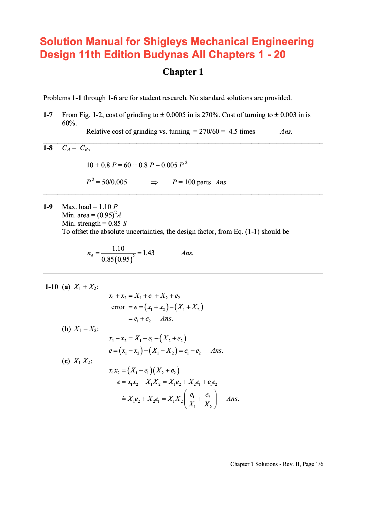
Solution Manual for Shigley's Mechanical Engineering Design 11...

An Introduction to Mechanical Engineering 4th Edition By Jonat...

Quantum Mechanics II Advanced Topics, 2e by S. Rajasekar, R. V...

Quantum Mechanics I The Fundamentals, 2e by S. Rajasekar, R. V...
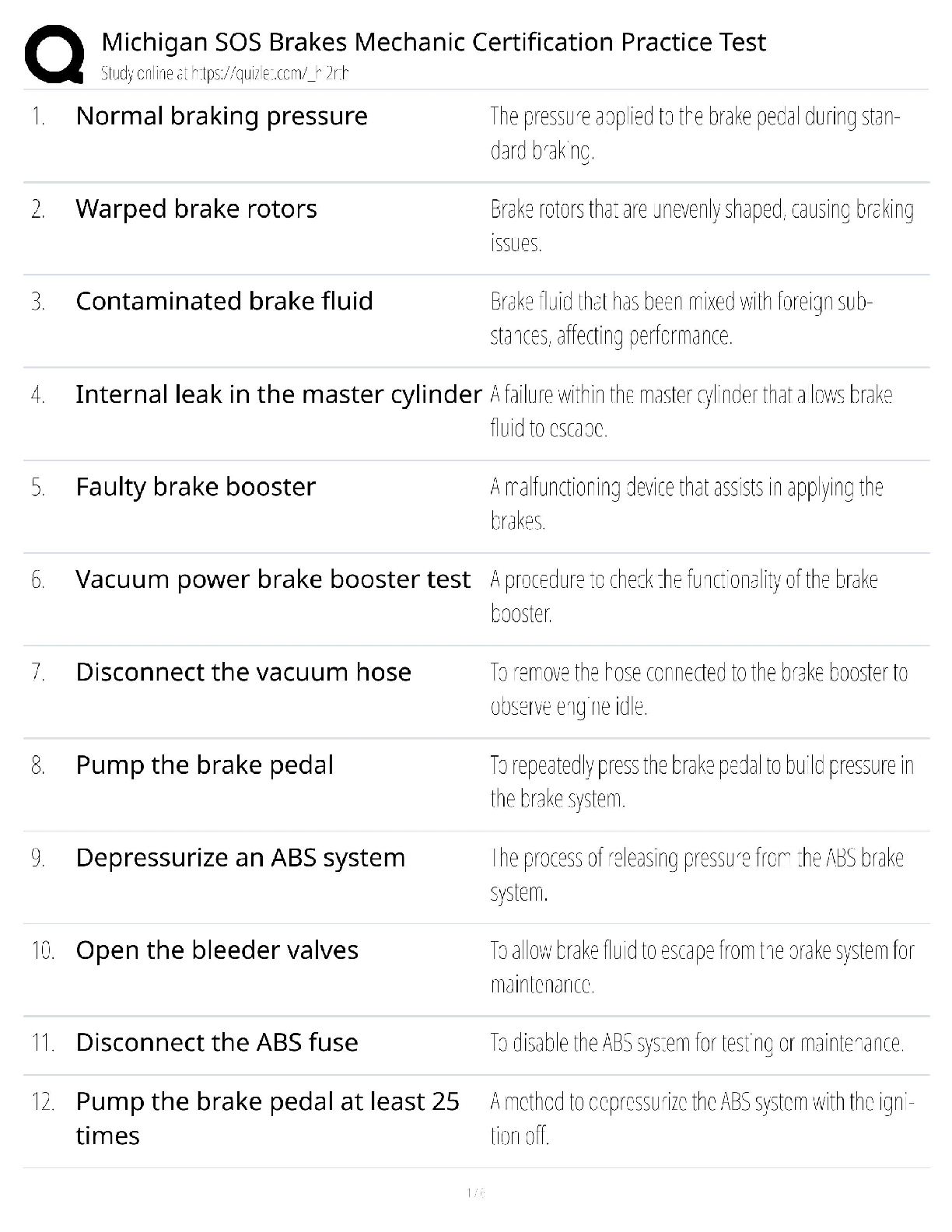
Michigan SOS Brakes / Mechanic Certification Practice Test / E...
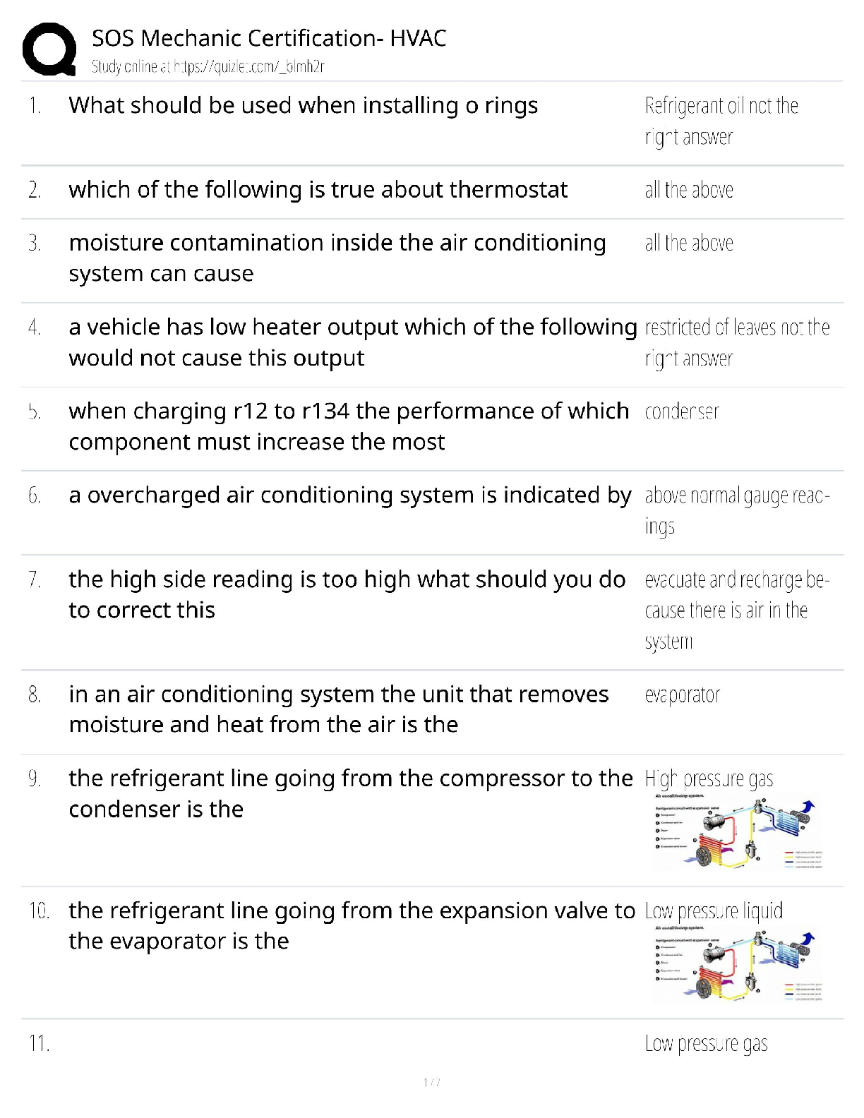
SOS Mechanic Certification - HVAC / HVACR Technician Exam / 20...
Solutions Manual For Advanced Mechanics of Materials and Appli...

Engineering & Technology Mechanical Engineering In the figur...


![Preview of Voleur HTB - Sensored Hashes & Password: [ENG] Voleur - Medium; To evaluate the security o](https://browseimages.nyc3.digitaloceanspaces.com/paper-images/2026/03/03/14wHb3dw2026-03-03-04-2869a6395647e75.png)