Engineering Mechanics > PROJECT REPORT > ME 314 Design and analyze a torsion bar suspension system PROJECT REPORT (All)
ME 314 Design and analyze a torsion bar suspension system PROJECT REPORT
Document Content and Description Below
Last updated: 8 months ago
Preview 5 out of 23 pages
Instant download

Loading document previews ...
Buy this Document to get the Full Access Instantly
Provided by Students Who Aced it
We Verify Document Content to Gurantee Accuracy
Reviews( 0 )
Document information
Connected school, study & course
About the document
Uploaded On
Feb 20, 2026
Number of pages
23
Written in
All

Additional information
This document has been written for:
Uploaded
Feb 20, 2026
Downloads
0
Views
101
Topic Tags
Recommended For You
Get more on PROJECT REPORT »

Nuclear Systems Volume II Elements of Thermal Hydraulic Design...
Solutions Manual for Engineering Mechanics Statics 11th Editio...
Solutions Manual for Engineering Mechanics, Dynamics, 15th Edi...


solution manual for Theory and design for mechanical measureme...
Solutions Manual for Fundamentals of Engineering Economics, La...
Solutions Manual for Basic Fracture Mechanics and its Applicat...
Ch 6 Kinematics / Score 100% / New 2025 Update / Complete Stud...

EVITP TEST FINAL EXAM 2025 ACTUAL EXAM: Complete Questions & D...
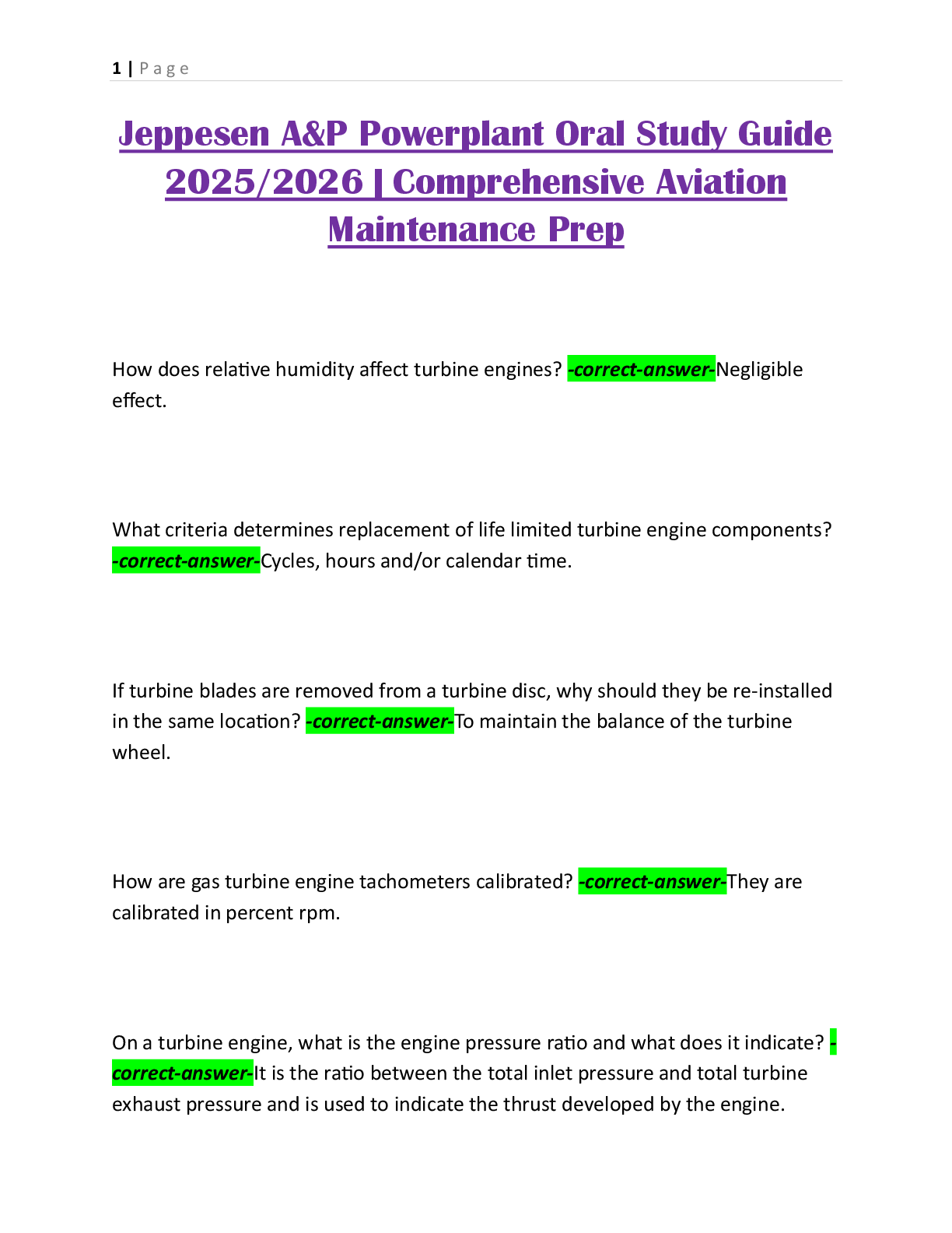
Jeppesen A&P Powerplant Oral Study Guide 2025/2026 | Comprehen...