Mechanical Engineering > Lab Report > COMPRESSION AND FLEXURE TEST OF CONCRETE LAB REPORT (All)
COMPRESSION AND FLEXURE TEST OF CONCRETE LAB REPORT
Document Content and Description Below
Last updated: 3 years ago
Preview 1 out of 19 pages
Instant download

Buy this Document to get the Full Access Instantly
Provided by Students Who Aced it
We Verify Document Content to Gurantee Accuracy
Reviews( 0 )
Document information
Connected school, study & course
About the document
Uploaded On
Jun 28, 2021
Number of pages
19
Written in
All

Additional information
This document has been written for:
Uploaded
Jun 28, 2021
Downloads
0
Views
230
Document Keyword Tags
Recommended For You
Get more on Lab Report »

Compression and Flexure Test of Concrete lab report ( WELL WRI...


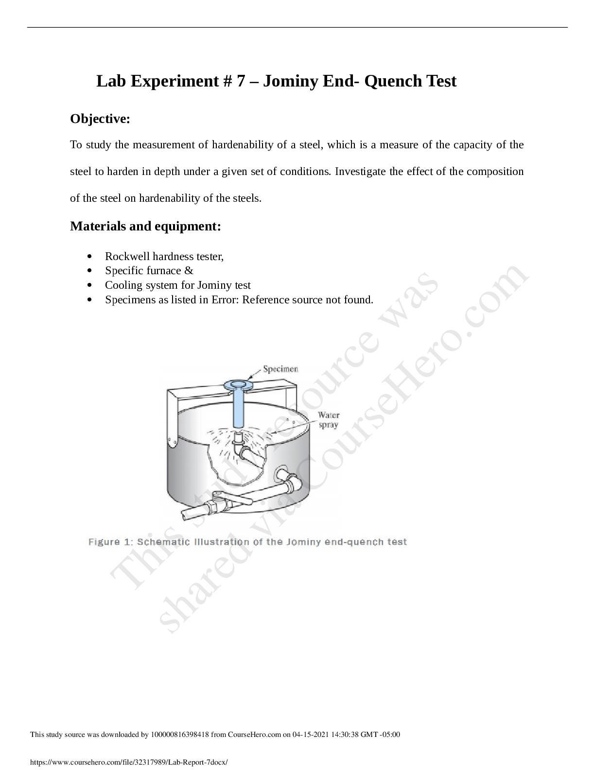
The City College of New York, CUNY - ME 461Lab Report #7 Jomi...

Quantum Mechanics II Advanced Topics, 2e by S. Rajasekar, R. V...

Quantum Mechanics I The Fundamentals, 2e by S. Rajasekar, R. V...

Design of Hydrodynamic Machines Pumps and Hydro-Turbines, 1e G...

Quenching and Tempering of Steel The City College of New York,...
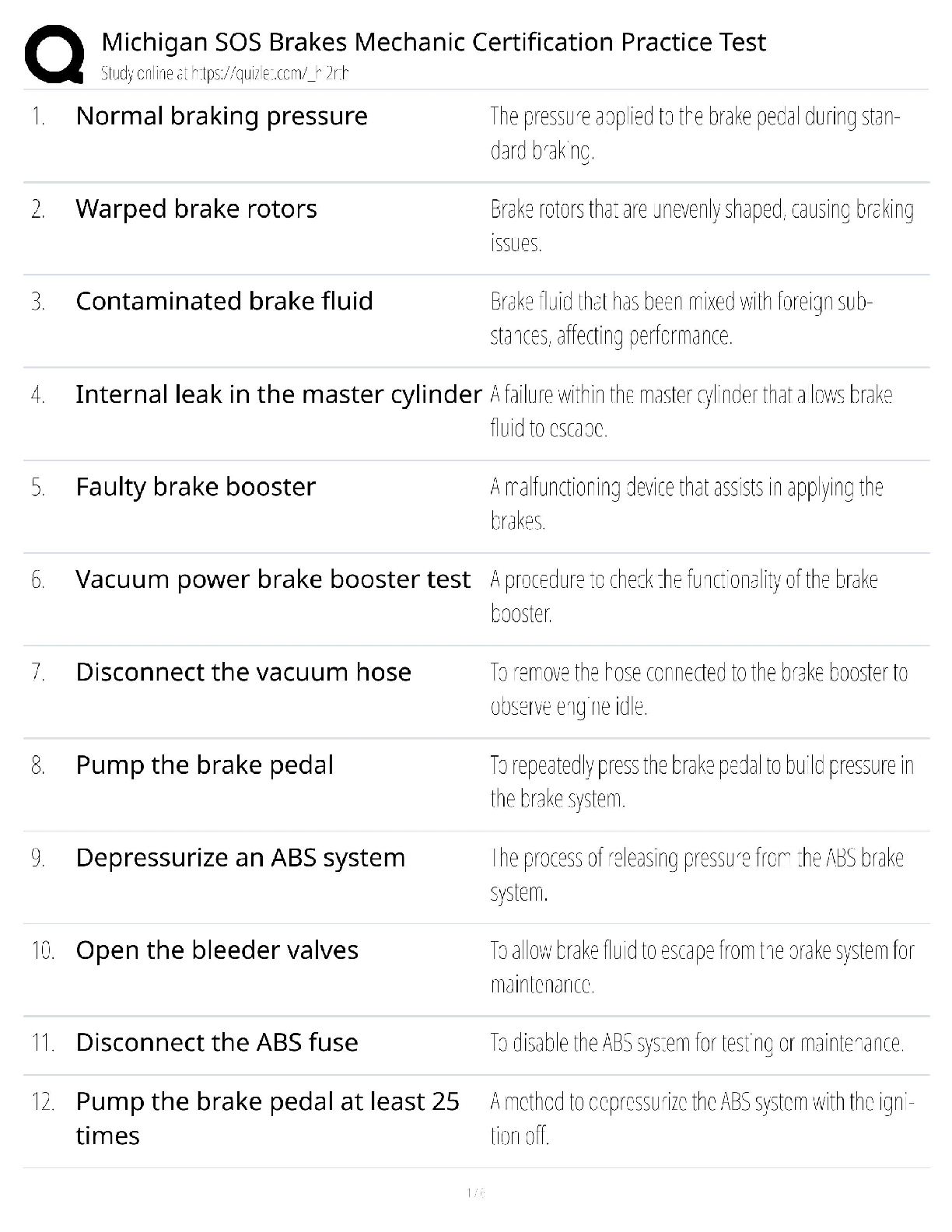
Michigan SOS Brakes / Mechanic Certification Practice Test / E...
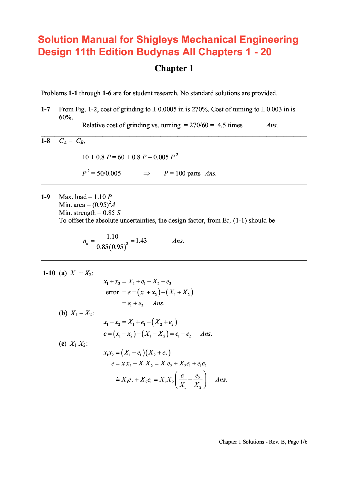
Solution Manual for Shigley's Mechanical Engineering Design 11...