SCIENCE 101 > Lab Report > HST 701 HISTORY OF SCIENCE AND TECH FOR THE 20TH CENTURY_Ryerson University_ Lab 8: Sluice Gate and (All)
HST 701 HISTORY OF SCIENCE AND TECH FOR THE 20TH CENTURY_Ryerson University_ Lab 8: Sluice Gate and Specific Energy
Document Content and Description Below
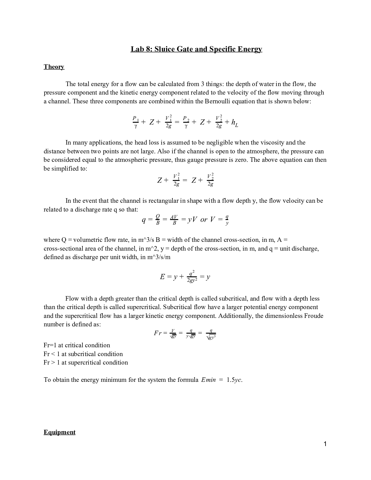
Lab 8: Sluice Gate and Specific EnergyHST 701 HISTORY OF SCIENCE AND TECH FOR THE 20TH CENTURY_Ryerson University_ Lab 8: Sluice Gate and Specific Energy Lab 8: Sluice Gate and Specific Energy Theory ... The total energy for a flow can be calculated from 3 things: the depth of water in the flow, the pressure component and the kinetic energy component related to the velocity of the flow moving through a channel. These three components are combined within the Bernoulli equation that is shown below: Z Pγ 1 + + 2g V 12 = Z Pγ 2 + + 2g V 22 + h L In many applications, the head loss is assumed to be negligible when the viscosity and the distance between two points are not large. Also if the channel is open to the atmosphere, the pressure can be considered equal to the atmospheric pressure, thus gauge pressure is zero. The above equation can then be simplified to: Z + Z 2g V 12 = + 2g V 22 In the event that the channel is rectangular in shape with a flow depth y, the flow velocity can be related to a discharge rate q so that: q = QB = ABV = yV or V = qy where Q = volumetric flow rate, in m^3/s B = width of the channel cross-section, in m, A = cross-sectional area of the channel, in m^2, y = depth of the cross-section, in m, and q = unit discharge, defined as discharge per unit width, in m^3/s/m E = y + 2qg2y2 = y Flow with a depth greater than the critical depth is called subcritical, and flow with a depth less than the critical depth is called supercritical. Subcritical flow have a larger potential energy component and the supercritical flow has a larger kinetic energy component. Additionally, the dimensionless Froude number is defined as: F r = V √gy = q y√gy = q g√ y3 Fr=1 at critical condition Fr < 1 at subcritical condition Fr > 1 at supercritical condition To obtain the energy minimum for the system the formula Emin = 1.5yc. Equipment 1● 1 open flow channel with sluice gate control ● 1 phone stopwatch ● 1 measuring tape ● 1 G.U.N.T Hydraulic bench ● Figure 1: The G.U.N.T apparatus used to conduct the lab. Procedure ● The overshot weir was set to about 2 cm in height. The undershot weir was raised to the highest level. ● The hydraulic bench was started and a steady flow was maintained at a low flow rate. ● Adjusted the height of the overshot weir to create a uniform flow within the channel, where the upstream and downstream depths were within 5% of each other. Measured the flow depth at this point. ● Measured the channel width and determined the flow rate of the channel in duplicates. The average of the two measurements was used to establish the unit discharge. ● Set the heights of the undershot weir, yg, to several positions, started from high to low and created 10 evenly-spaced measurements. In this experiment increments of 7mm were used. ● For each of the positions, the values were recorded for y1,y2 and yg into table 1. Computation and Data Analysis Establishment of a steady-state, uniform flow Position of overshot weir 2.5mm Upstream flow depth 3.85mm Downstream flow depth 3.85mm 2Percent Flow Different 0% Determination of Unit discharge with the Volumetric Storage Tank [Show More]
Last updated: 8 months ago
Preview 1 out of 7 pages
Buy this document to get the full access instantly
Instant Download Access after purchase
Buy NowInstant download
We Accept:

Reviews( 0 )
$8.00
Can't find what you want? Try our AI powered Search
Document information
Connected school, study & course
About the document
Uploaded On
Apr 05, 2023
Number of pages
7
Written in
All

Additional information
This document has been written for:
Uploaded
Apr 05, 2023
Downloads
0
Views
134


.png)


.png)