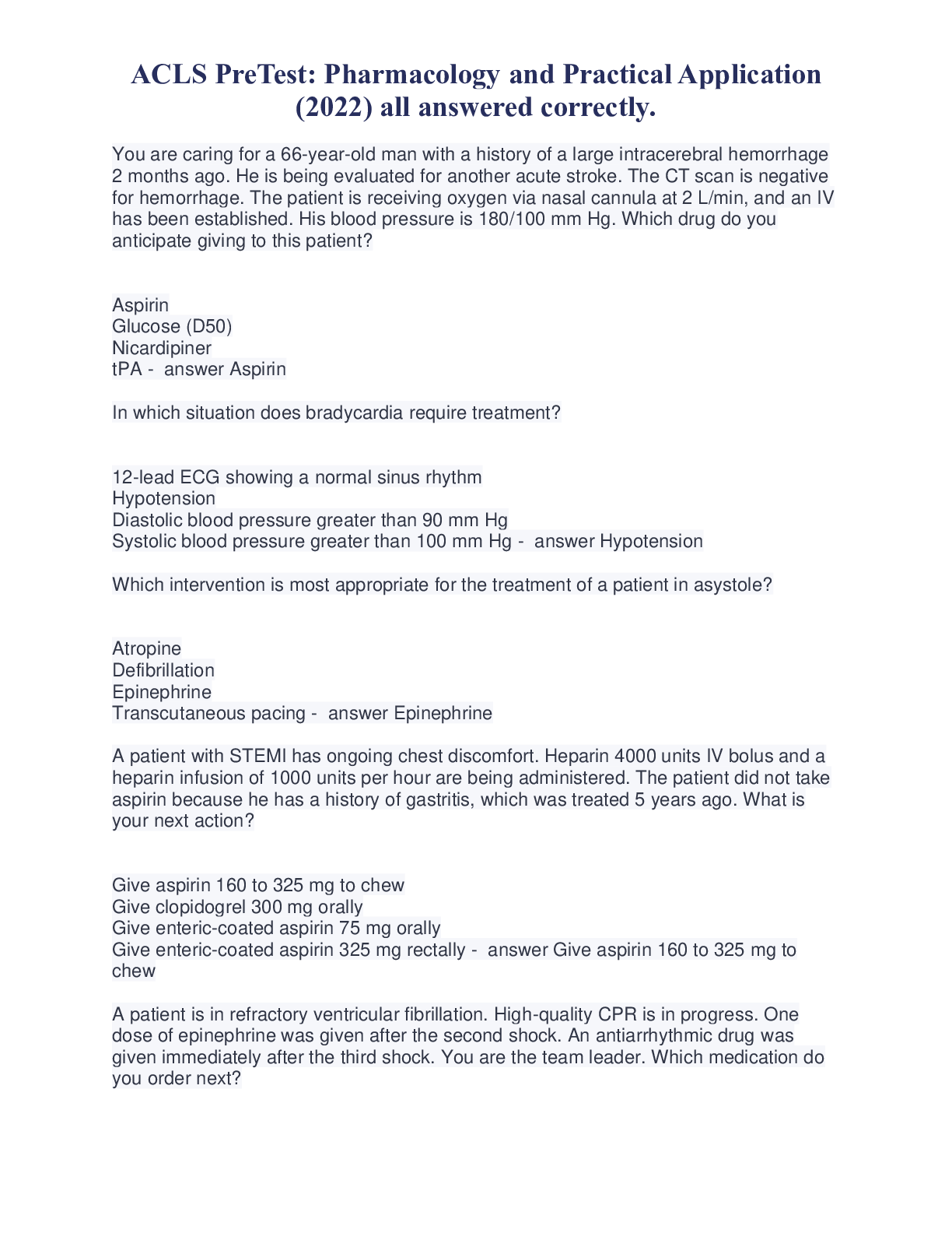
ACLS PreTest: Pharmacology and Practical Application (2022) all answered correctly.
$ 15
Test Bank for Corporate Finance, 12th Edition by Stephen A. Ross, Randolph W. Westerfield, Jeffrey F. Jaffe & Bradford D. Jordan | ISBN: 9781260091878 | Complete Chapters 1-27 | Q&A | Downloadable PDF
$ 20

HESI A2 2020 LATEST VERSION
$ 11
Test_bank_for_paramedic_care_principles_and_practice,_6th_edition
$ 15
YOOST CHAPTER 35 MEDICATION ADMINISTRATION REVIEW QUESTIONS & FLASHCARDS
$ 15

AQA A-level ECONOMICS 7136/3 PAPER 3 ECONOMIC PRINCIPLES AND ISSUES Mark scheme June 2020
$ 7.5
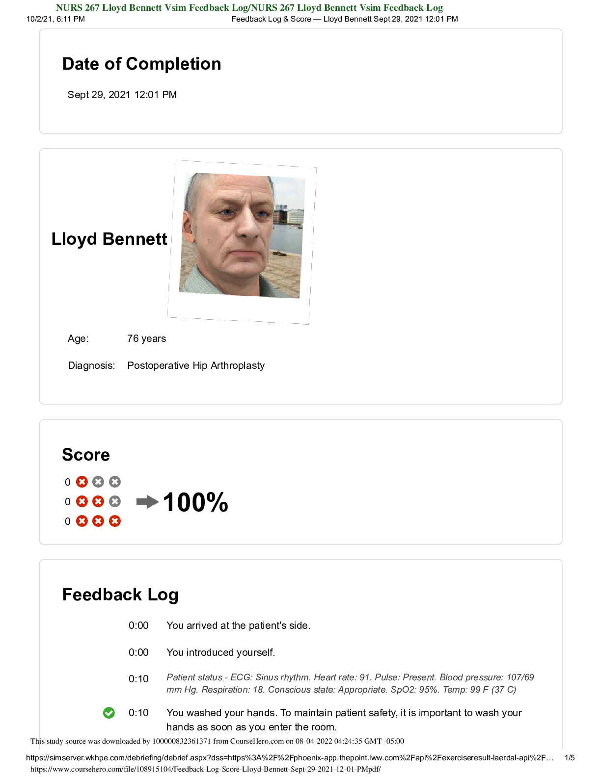
NURS 267 Lloyd Bennett Vsim Feedback Log/NURS 267 Lloyd Bennett Vsim Feedback Log
$ 7

Foundations of Economics 9th Edition By Robin Bade, Michael Parkin (Test Bank All Chapters)
$ 25
Personally Identifiable
$ 3

Summary C12 - Business Law Case Analysis 3 Securities and Exchange Commission v. Edwards - Ashworth College
$ 10
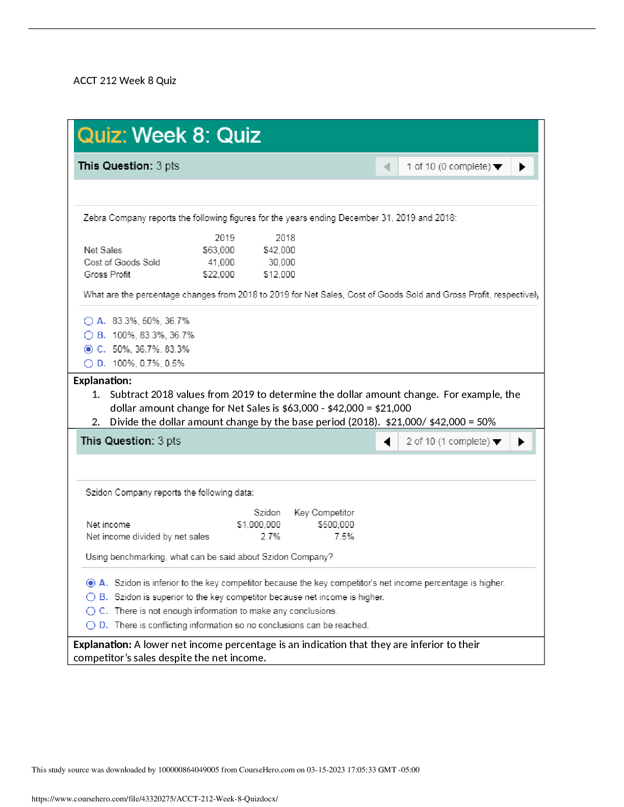
ACCT 212 Week 8 Quiz Answered
$ 8
Test Bank for Essentials of Economics, 9th Edition by N. Gregory Mankiw | All Chapters 1-24 | Complete Questions & Answers | Downloadable PDF
$ 19
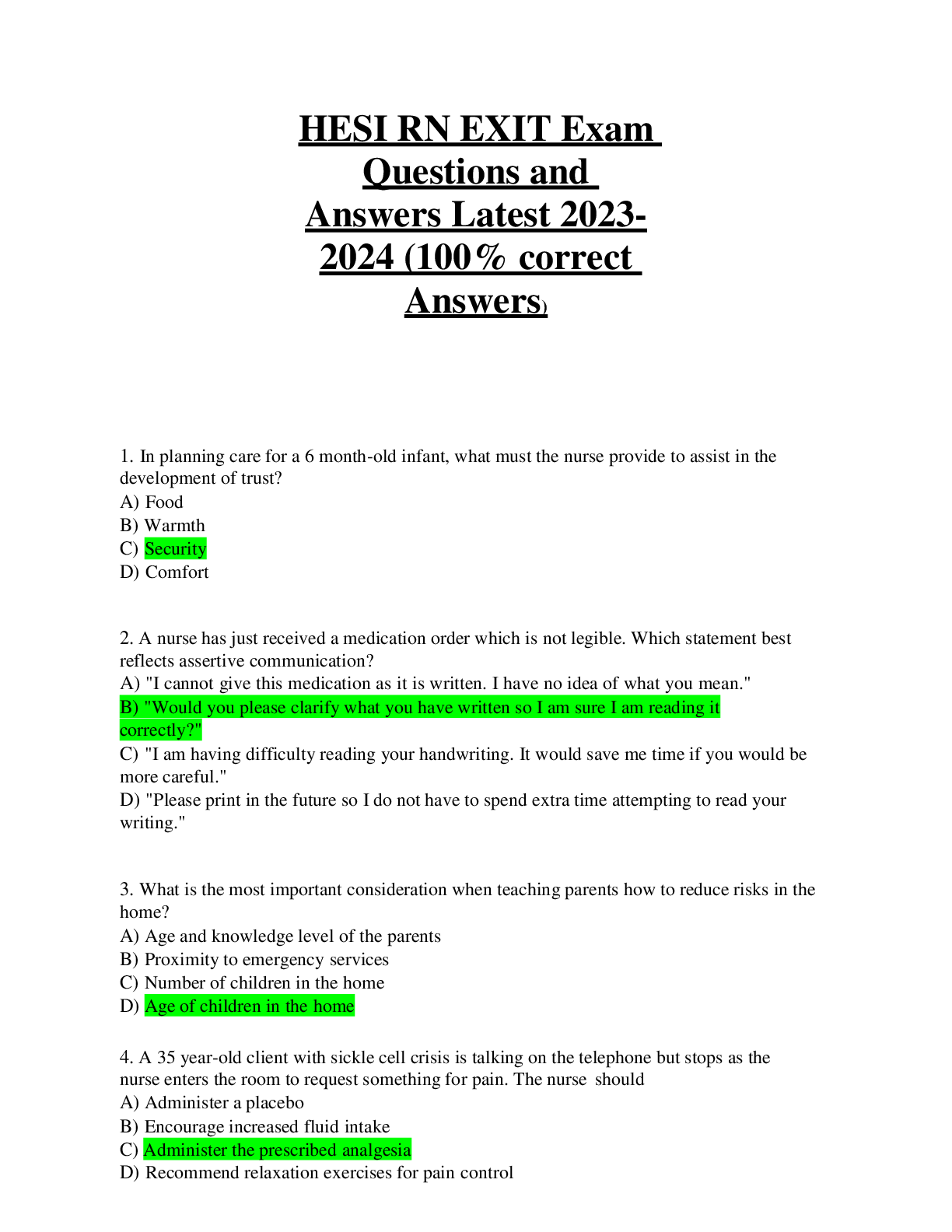
HESI RN EXIT Exam Questions and Answers Latest 2023-2024 (100% correct Answers)


.png)

.png)


.png)


.png)
.png)


.png)


.png)

.png)
