Lab-7 (LK) Series Circuit
Objective
1. Learn to build up a series circuit and a parallel circuit with three resistors and one DC
source.
2. Measure current passing through each resistor, and measure the voltage acros
...
Lab-7 (LK) Series Circuit
Objective
1. Learn to build up a series circuit and a parallel circuit with three resistors and one DC
source.
2. Measure current passing through each resistor, and measure the voltage across each
resistor.
3. Verify the equations of series and parallel circuits.
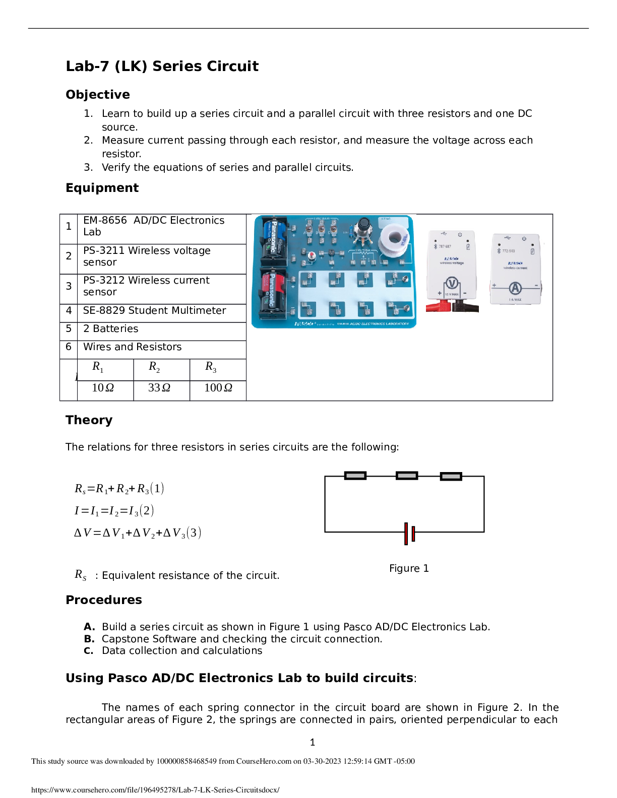
Equipment
1 EM-8656 AD/DC Electronics
Lab
2 PS-3211 Wireless voltage
sensor
3 PS-3212 Wireless current
sensor
4 SE-8829 Student Multimeter
5 2 Batteries
6 Wires and Resistors
R
R
1 R2 R3
10Ω 33Ω 100Ω
Theory
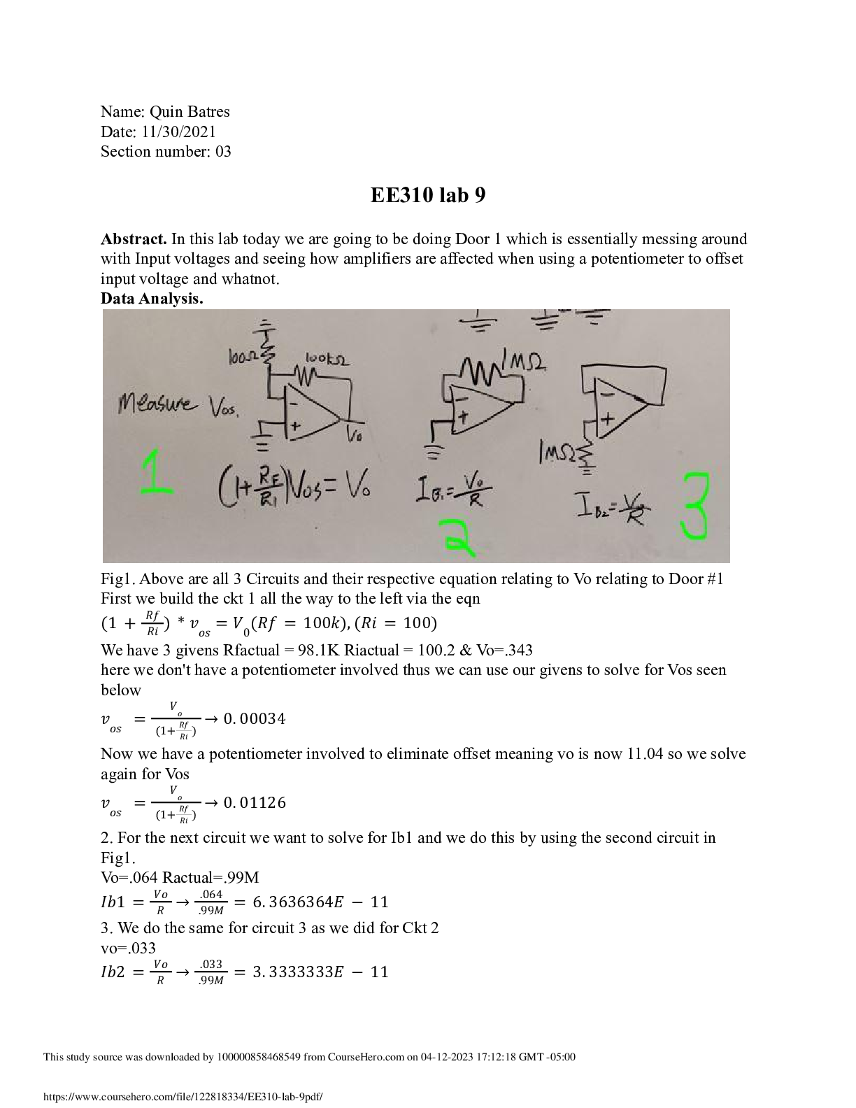
The relations for three resistors in series circuits are the following:
R
s=R1+R2+R3(1)
I=I1=I2=I3(2)
∆V=∆V1+∆V2+∆V3(3)
R
S : Equivalent resistance of the circuit.
Procedures
A. Build a series circuit as shown in Figure 1 using Pasco AD/DC Electronics Lab.
B. Capstone Software and checking the circuit connection.
C. Data collection and calculations
Using Pasco AD/DC Electronics Lab to build circuits:
The names of each spring connector in the circuit board are shown in Figure 2. In the
rectangular areas of Figure 2, the springs are connected in pairs, oriented perpendicular to each
1
Figure 1
This study source was downloaded by 100000858468549 from CourseHero.com on 03-30-2023 12:59:14 GMT -05:00
https://www.coursehero.com/file/196495278/Lab-7-LK-Series-Circuitsdocx/
other and named C and S. In a given rectangular area, the two springs should be treated equally
in circuit connection. For example, connecting to C1 means connecting to S1 also. Therefore the
names C1 and S1 are interchangeable in the following circuit build procedures. Similarly for C2
and S2.
Figure 2: Definition of the names of each spring connector
Procedure A: Build a circuit as shown in Figure 1 using Pasco AD/DC
Electronics Lab.
1. Check Battery and put two batteries into the Battery Holder
Use the multimeter to check the values of each battery (battery-1 across B1 and B2; and
battery-2 across B3 and B4). The value of each battery should be close to 1.5V. The B2 wire
should connect to B3 (two batteries connected together), and record the DC voltage between
B1 and B4 in the data table.
2 Build a series circuit:
2.1 B4 wire connects to J4
2.2 B1 wire connects to J8
2.3 C4 wire connects to C3
2.4 S3 R1 connects to S2
2.5 C2 wire connects to C1
2.6 S1 R2 connects to S5
2.7 C5 wire connects to C6
2.8 S6 R3 connects to S7
2.9 C7 wire connects to C8
Figure 3: Circuit connections
Procedure B: Capstone Software and checking the circuit connection.
1 Check whether the total number of wires and resistors in your circuit is 9. If it is not, please
check step A2 (wire between B2 and B3 does not count).
[Show More]


.png)


![Preview of eBook [PDF] College Physics A Strategic Approach Plus Mastering Physics 4th Edition By Ran](https://scholarfriends.com/storage/Kg1C7KaB2026-05-08-11-3169fe48322ad11.png)