Engineering > Study Notes > University of Texas - CE 335CompressionMembers (All)
University of Texas - CE 335CompressionMembers
Document Content and Description Below
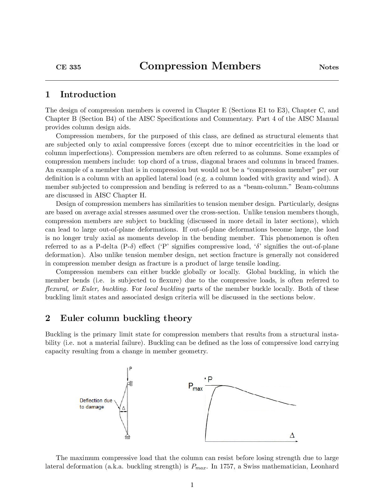
CE 335 Compression Members Notes 1 Introduction The design of compression members is covered in Chapter E (Sections E1 to E3), Chapter C, and Chapter B (Section B4) of the AISC Specifications and C ... ommentary. Part 4 of the AISC Manual provides column design aids. Compression members, for the purposed of this class, are defined as structural elements that are subjected only to axial compressive forces (except due to minor eccentricities in the load or column imperfections). Compression members are often referred to as columns. Some examples of compression members include: top chord of a truss, diagonal braces and columns in braced frames. An example of a member that is in compression but would not be a \compression member" per our definition is a column with an applied lateral load (e.g. a column loaded with gravity and wind). A member subjected to compression and bending is referred to as a \beam-column." Beam-columns are discussed in AISC Chapter H. Design of compression members has similarities to tension member design. Particularly, designs are based on average axial stresses assumed over the cross-section. Unlike tension members though, compression members are subject to buckling (discussed in more detail in later sections), which can lead to large out-of-plane deformations. If out-of-plane deformations become large, the load is no longer truly axial as moments develop in the bending member. This phenomenon is often referred to as a P-delta (P-δ) effect (‘P’ signifies compressive load, ‘δ’ signifies the out-of-plane deformation). Also unlike tension member design, net section fracture is generally not considered in compression member design as fracture is a product of large tensile loading. Compression members can either buckle globally or locally. Global buckling, in which the member bends (i.e. is subjected to flexure) due to the compressive loads, is often referred to flexural, or Euler, buckling. For local buckling parts of the member buckle locally. Both of these buckling limit states and associated design criteria will be discussed in the sections below. 2 Euler column buckling theory Buckling is the primary limit state for compression members that results from a structural instability (i.e. not a material failure). Buckling can be defined as the loss of compressive load carrying capacity resulting from a change in member geometry. The maximum compressive load that the column can resist before losing strength due to large lateral deformation (a.k.a. buckling strength) is Pmax. In 1757, a Swiss mathematician, Leonhar [Show More]
Last updated: 3 years ago
Preview 1 out of 32 pages
Buy this document to get the full access instantly
Instant Download Access after purchase
Buy NowInstant download
We Accept:

Reviews( 0 )
$7.00
Can't find what you want? Try our AI powered Search
Document information
Connected school, study & course
About the document
Uploaded On
Apr 15, 2021
Number of pages
32
Written in
All

Additional information
This document has been written for:
Uploaded
Apr 15, 2021
Downloads
0
Views
182


.png)